Has anyone ever had an igniter fail on the 96-02 v6 4Runner? Can someone explain to me the symptoms? Is this a common failure? I am almost certain that my igniter failed. My Tachometer has some funny readings and the truck wont shift gears on a regular basis normally. Plus I have a "P 1300" Code. I'm hoping this fixes my problem and it's not a physical tranny problem. I have already had the ECU replaced, and that is one of the things to replace for the "fixes" for a 1300 code. Any input is well appreciated.

You are using an out of date browser. It may not display this or other websites correctly.
You should upgrade or use an alternative browser.
You should upgrade or use an alternative browser.
Igniter Failure?
- Thread starter Xandarin
- Start date
Register to hide this ad

duzuck
New member
DTC P1300: Ignitor Circuit Malfunction
Caution: If ECM replacement is instructed in following testing, always ensure ECM connectors and ground circuit are okay. If either are suspect, repair and repeat testing to confirm ECM malfunction.
Circuit Description
The ECM determines ignition timing and outputs ignition signals (IGT) for each cylinder. Based on IGT signals, the ignitor controls the primary ignition signals (IGC) for all ignition coils. The ignitor also sends an ignition confirmation signal (IGF) as a fail-safe measure to the ECM. DTC is set when there is no IGF signal to ECM for 6 consecutive signals during engine operation. Possible causes are:
- IGF of IGT open or short circuit from ignitor to ECM
- Ignitor
- ECM
Diagnosis & Repair
1) Check for spark at misfiring cylinder. To check for spark, remove all spark plugs, and ground out each removed spark plug on block and crank engine for no more than 5 seconds. Test this method on each spark plug wire. If spark is present, go to step. If spark is not present, go to step 4)
2) Check for open or short in IGF circuit (Black/Yellow wire) between ECM and ignitor. Ignitor is located near MAF sensor. Repair wiring as necessary. If circuit is OK, go to next step
3) Disconnect black 10-pin ignitor connector. Access ECM behind glove box. Turn ignition on. On A/T models, measure voltage between ground and terminal no. 12 (black/yellow wire) at ECM E9 connector (see figure). On M/T models, measure voltage between ground and terminal no. 17 (black/yellow wire) at ECM E5 connector (see figure). On all models, if voltage is 4.5-5.5 volts, replace ignitor. If voltage is not 4.5-5.5 volts, replace ECM and retest.
4) Check for open or short in IGT1, IGT2 and IGT3 circuits between ECM and ignitor. Wiring colours for IGT1 is BLK/BLU, IGT2 is BRN/YEL, and IGT3 is BLK/WHT, and they're part of a 10-pin connector into the ignitor (which is on the right side of the engine compartment). Repair wiring as necessary. If circuits are OK, go to next step.
5) Access ECM behind glove box. On A/T models, measure voltage between ground and terminals no. 24 (BLK/BLU), no. 25 (BRN/YEL) and no. 26 (BLK/WHT) at ECM E9 connector. On M/T models, measure voltage between ground and terminals no. 23, no. 22, and no. 21 (same colours as above) at ECM E5 connector. On all models, if voltage is .1-4.5 volts, go to next step. If voltage is not .1-4.5 volts, replace ECM and retest.
6) Disconnect Black 10-pin ignitor connector. Backprobe ECM connector. Do same test as step 5) (three-wire voltage test). If voltage is not within specified range, replace ECM and retest.
7) Turn ignition on. Measure voltage between ground and terminal no. 9 (BLK/RED wire) at ignitor wiring harness connector. If voltage is 9-14 volts, go to next step. If voltage is not 9-14 volts, check and repair ignitor power source circuirt.
8) Check for open or short in wiring harness between ignition switch and ignition coil, and between ignition coil and ignitor. Repair wiring as necessary. If wiring harness is OK, check ignition coil - turn ignition on, check for battery voltage at ignitor and ignition coil positive terminal. If voltage exists, go to next step. If not, check wiring between ignition switch, ignition coil, and ignitor. Next, check ignition coil resistance. Replace ignition coil if not within specs. Replace coil as necessary. If coil is OK, replace ignitor.
E5 and E9 diagrams to follow
Caution: If ECM replacement is instructed in following testing, always ensure ECM connectors and ground circuit are okay. If either are suspect, repair and repeat testing to confirm ECM malfunction.
Circuit Description
The ECM determines ignition timing and outputs ignition signals (IGT) for each cylinder. Based on IGT signals, the ignitor controls the primary ignition signals (IGC) for all ignition coils. The ignitor also sends an ignition confirmation signal (IGF) as a fail-safe measure to the ECM. DTC is set when there is no IGF signal to ECM for 6 consecutive signals during engine operation. Possible causes are:
- IGF of IGT open or short circuit from ignitor to ECM
- Ignitor
- ECM
Diagnosis & Repair
1) Check for spark at misfiring cylinder. To check for spark, remove all spark plugs, and ground out each removed spark plug on block and crank engine for no more than 5 seconds. Test this method on each spark plug wire. If spark is present, go to step. If spark is not present, go to step 4)
2) Check for open or short in IGF circuit (Black/Yellow wire) between ECM and ignitor. Ignitor is located near MAF sensor. Repair wiring as necessary. If circuit is OK, go to next step
3) Disconnect black 10-pin ignitor connector. Access ECM behind glove box. Turn ignition on. On A/T models, measure voltage between ground and terminal no. 12 (black/yellow wire) at ECM E9 connector (see figure). On M/T models, measure voltage between ground and terminal no. 17 (black/yellow wire) at ECM E5 connector (see figure). On all models, if voltage is 4.5-5.5 volts, replace ignitor. If voltage is not 4.5-5.5 volts, replace ECM and retest.
4) Check for open or short in IGT1, IGT2 and IGT3 circuits between ECM and ignitor. Wiring colours for IGT1 is BLK/BLU, IGT2 is BRN/YEL, and IGT3 is BLK/WHT, and they're part of a 10-pin connector into the ignitor (which is on the right side of the engine compartment). Repair wiring as necessary. If circuits are OK, go to next step.
5) Access ECM behind glove box. On A/T models, measure voltage between ground and terminals no. 24 (BLK/BLU), no. 25 (BRN/YEL) and no. 26 (BLK/WHT) at ECM E9 connector. On M/T models, measure voltage between ground and terminals no. 23, no. 22, and no. 21 (same colours as above) at ECM E5 connector. On all models, if voltage is .1-4.5 volts, go to next step. If voltage is not .1-4.5 volts, replace ECM and retest.
6) Disconnect Black 10-pin ignitor connector. Backprobe ECM connector. Do same test as step 5) (three-wire voltage test). If voltage is not within specified range, replace ECM and retest.
7) Turn ignition on. Measure voltage between ground and terminal no. 9 (BLK/RED wire) at ignitor wiring harness connector. If voltage is 9-14 volts, go to next step. If voltage is not 9-14 volts, check and repair ignitor power source circuirt.
8) Check for open or short in wiring harness between ignition switch and ignition coil, and between ignition coil and ignitor. Repair wiring as necessary. If wiring harness is OK, check ignition coil - turn ignition on, check for battery voltage at ignitor and ignition coil positive terminal. If voltage exists, go to next step. If not, check wiring between ignition switch, ignition coil, and ignitor. Next, check ignition coil resistance. Replace ignition coil if not within specs. Replace coil as necessary. If coil is OK, replace ignitor.
E5 and E9 diagrams to follow
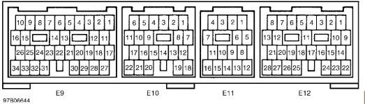

duzuck
New member
I got all of this info. from Mitchell On-Demand workshop manual. I gotta protect my ass here, and state that you can take this information and use it at your own will, and should you choose to perform the work, you and only you are responsible for any successes / problems. Remember, my advice is free, and you get what you pay for.
This sounds like a hell of a job for someone not very-well acquainted with Toyota electrical systems. From the info, I feel that I could tackle the job, but if I wanted it done quick, I'd take it to a stealership. I guess you're looking at either replacing your ECM (again), your ignitor, a coil or simply repairing some wiring. There is more to testing the igntion system, like checking the Crank position sensor, among other things. I tried to extract the info that would be relevant to your case however. You should try to search for a more complete checklist for testing the igntion system. It also involves checking the resistance of certain electrical components.
Well, I've done my best to help you. You'll probably end up taking this to a shop to get it fixed, because it looks very intimidating. I guess if you dont mind getting your hands dirty, have a second vehicle to get you around, and there's no rush to complete, you may tackle this job yourself. That's up to you.
Good luck man!
This sounds like a hell of a job for someone not very-well acquainted with Toyota electrical systems. From the info, I feel that I could tackle the job, but if I wanted it done quick, I'd take it to a stealership. I guess you're looking at either replacing your ECM (again), your ignitor, a coil or simply repairing some wiring. There is more to testing the igntion system, like checking the Crank position sensor, among other things. I tried to extract the info that would be relevant to your case however. You should try to search for a more complete checklist for testing the igntion system. It also involves checking the resistance of certain electrical components.
Well, I've done my best to help you. You'll probably end up taking this to a shop to get it fixed, because it looks very intimidating. I guess if you dont mind getting your hands dirty, have a second vehicle to get you around, and there's no rush to complete, you may tackle this job yourself. That's up to you.
Good luck man!
Wow, thanks a lot! I've been reading up at the toyota website, TIS and got their repair manuals. It says mostly the same stuff, but a few things are different. You said that if the igniter to ECU (Yellow/Black Wire) reads 4.5-5.5 to replace it. Sure it doesnt mean if it IS NOT 4.5-5.5 to replace it? I've tested a lot of stuff with my multimeter now and there is still a whole lot I could test, but the only funny reading I've found is on the igniter. So I dunno, I have one on order, if that doesn't fix it I'm going to take it in to get ripped off  . Thanks for all the info!
. Thanks for all the info!
duzuck
New member
I double checked the info. and it says exactly what I put; if voltage is one reading, replace one part, if not, replace another.
I find it a little strange though, because either way, something needs to be replaced. It honestly doesn't make sense when I think about it, because you have to get some reading, even if it's zero. So everybody's 4Runner will give a reading at this pin as well, but they wouldn't have to replace a part. That's just what it says though.
Good luck. Kudos for doing this yourself, you're obviously not afraid to get your hands dirty. Let me know what the problem was when you get it fixed.
I find it a little strange though, because either way, something needs to be replaced. It honestly doesn't make sense when I think about it, because you have to get some reading, even if it's zero. So everybody's 4Runner will give a reading at this pin as well, but they wouldn't have to replace a part. That's just what it says though.
Good luck. Kudos for doing this yourself, you're obviously not afraid to get your hands dirty. Let me know what the problem was when you get it fixed.
Again I appreciate all your info. I will definately let you know how it works out. I'm like 90% sure it's the igniter now. I took some more readings today and played with it some. I had the connection to the valve body on the tranny disconnected in order to manually shift the truck to get it home and once I reconnected it i retested the igniter to ecm connection and it read 5.03 just like the manuals said. So it makes a lot of sense. My tach goes crazy and the truck doesnt rev up all the way when i slam the gas in park. The igniter sends the tachometer signal to the computer (per the truck's wiring diagram), and I have a bad reading there. The Tranny rarely ever shifts out of first gear, and if the igniter is telling the computer that I'm only at 1500 RPM it will never shift, right? I sure hope so. LOL. We'll see...:biggrin2:
Well If anyone has been following this problem, it seems a rodent or some sort of animal or something along those lines crawled up on top of my tranny and "rubbed" the insulation off of the wiring going to my tranny. I can't take credit for finding it, my stealership found it and fixed it. I spent an entire weekend hunting for the ground and flat out gave up. I had my whole dash ripped out and my wiring harness opened up. Even after I replaced my comptuer and ECU, nothing helped. So who knows what caused it, maybe its normal but I doubt it. So, if anyone has the symptoms I had, DONT take it to a transmission shop, and if you do, DONT have them replace your tranny because its simply not broke!
I would have had my tranny replaced, Computer replaced, Igniter replaced, and then turn around and find out its just two supid wires that grounded out. Go figure... 250 bucks worth of labor VS $5000 bucks in parts and labor.
I would have had my tranny replaced, Computer replaced, Igniter replaced, and then turn around and find out its just two supid wires that grounded out. Go figure... 250 bucks worth of labor VS $5000 bucks in parts and labor.
Wallrunner
New member
No Spark
Hey guys, I’ve been scrolling through old threads looking for some sort of insight into this crazy problem in having.
I have a 1996 v6 4x4 Limited and after a throttle body cleaning and spark plug change I am no longer able to start the car.
Here’s how it all started...
I got the bright idea to give my throttle body a good cleaning. I removed everything and the cleaning went great. I had a nice clean throttle body ready to go and I thought to myself.. “let’s change the spark plugs and wires!”
Got the car all out back together and now it won’t start.. i know I am getting fuel because after a few tries at starting I can smell the gas... I checked all my wires and still nothing...
I’m at a loss for words because I’ve never had an issue like this for something this simple..
Any insight would help a ton.. I’ve researched for two weeks and can’t get my baby back on the road..
Hey guys, I’ve been scrolling through old threads looking for some sort of insight into this crazy problem in having.
I have a 1996 v6 4x4 Limited and after a throttle body cleaning and spark plug change I am no longer able to start the car.
Here’s how it all started...
I got the bright idea to give my throttle body a good cleaning. I removed everything and the cleaning went great. I had a nice clean throttle body ready to go and I thought to myself.. “let’s change the spark plugs and wires!”
Got the car all out back together and now it won’t start.. i know I am getting fuel because after a few tries at starting I can smell the gas... I checked all my wires and still nothing...
I’m at a loss for words because I’ve never had an issue like this for something this simple..
Any insight would help a ton.. I’ve researched for two weeks and can’t get my baby back on the road..
Last edited:

LittleCaesar
New member
A thirteen year old thread resurrection, nice.
First off, do you have spark at any of the wires? My guess is the wires aren’t in the correct order if it was working beforehand. Did you check the igniter connector?
First off, do you have spark at any of the wires? My guess is the wires aren’t in the correct order if it was working beforehand. Did you check the igniter connector?
p1300 po300 po301 codes
My son, with a 01 4runner had the above codes.
It wasn't the ignitor, spark plug, computer or any of that. It was a bad negative terminal on the battery. Poor ground. Ours was really bad. The wire was corroded with battery acid for more than 8" away from the battery.
Cut the bad wire off,
Cleaned wire with baking soda solution and compressed air
Put new terminal on the battery and cable
Started engine- The miss was gone and the light was off. Problem solved. 6 bucks!
Check for simple things before buying components.
My son, with a 01 4runner had the above codes.
It wasn't the ignitor, spark plug, computer or any of that. It was a bad negative terminal on the battery. Poor ground. Ours was really bad. The wire was corroded with battery acid for more than 8" away from the battery.
Cut the bad wire off,
Cleaned wire with baking soda solution and compressed air
Put new terminal on the battery and cable
Started engine- The miss was gone and the light was off. Problem solved. 6 bucks!
Check for simple things before buying components.

Geology
New member
Just got the P1300 code as Runner died on the road suddenly.. crank, few kicks, but no start. It was shaky on startup for months and had thrown lots of P0300 and P0420 codes as it went bad.
It was one of the wires on the back of the ignitor, shook until metal fatigue got it. Wiring harness had disconnected from the intake/MAS allowing lots of flexure.
Check the ignitor wiring first, for me it was a simple pin swap and crimp to fix it. Looks like a lot of Toyotas have this problem.
It was one of the wires on the back of the ignitor, shook until metal fatigue got it. Wiring harness had disconnected from the intake/MAS allowing lots of flexure.
Check the ignitor wiring first, for me it was a simple pin swap and crimp to fix it. Looks like a lot of Toyotas have this problem.