Mystery Electrical Problem

4runnernyc

New member
Hi everyone. I just bought a 2005 SR5. The car is in great physical condition and has less than 30,000 miles on it! But, I bought it with one problem that I thought I would be able to figure out how to fix. After plenty of tinkering and several evenings spent combing through this forum, google, and service manuals, I'm stumped. On to the problem...

WHAT DOESN'T WORK:
1) All dome lights (i.e. in the front and rear cabin, and cargo area)
2) Keyless entry remotes generate zero response from the car
3) The AUTO feature on the driver's side window sometimes works (and the word "Auto" on the button sort of flickers when it's not working).
4) The radio clock resets to 1:00 every time I restart the car.

WHAT DOES WORK (In case it helps isolate the problem):
1) Power locks (when activated from the interior)
2) Sunroof
3) Power windows (including rear window)
4) Power mirrors
5) Rear wiper
6) Cupholder lights
7) Stereo (other than the clock reset issue noted above)

To short-circuit the obvious questions, I have continuity-tested EVERY fuse in the vehicle (interior and and under-hood fuse boxes), and I have swapped the "Dome" relay with another working relay to see if that was the culprit. It wasn't... I have also tested the battery on both keyless entry devices and both are in good working order.

Anyone have a similar experience and solution? Ideas? Thanks!!
 
Register to hide this ad
Have you inspected the wiring in the drivers kick plate for any evidence of modifications or chafing? I am not a Toyota technician, but I do troubleshoot electronic control systems for a living. I looked at my wiring diagrams a bit and here is what I came up with...

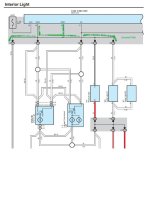
1. Dome lights: Do your dome lights work in ON, but not in DOOR? The interior lighting system is controlled by the Body ECU. The ILE (Interior Lighting Enable) signal is is used to supply ground to the lighting system when the lights should be on, if the switch is in DOOR. If the lights work in ON but not DOOR, the problem is likely the ILE signal. If they don't work at all, I would be more likely to suspect a broken 12V supply wire.

2. Keyless Entry: Keyless entry is controlled by a wireless receiver module that is mounted in the left rear-most pillar. This module has wiring that is routed up the drivers side of the vehicle (I think under the door sills according to my diagram.) to the Body ECU. The Body ECU then controls the actual lock actuators. Since the locks work when controlled from the interior, the signal from the Body ECU is working. It could be the signal between the wireless module and the body ECU.
3. Drivers Auto Window: This is a strange one... The master switch in the drivers door seems to be what control's the auto function. The associated wiring remains in the door and does not go through any other connectors. There is two lines that go out to the Body ECU to allow the Driver's Door Lock Cylinder to roll up or down the windows. The feature is listed on the system diagram spec sheet. I've never actually tried it out before. My guess here is potentially a loose connection on the driver's door window control switch assembly.
4. Radio Clock: The power that should keep the radio going comes from Radio Fuse #1 in the Engine Compartment Relay Box (Fuse Box).

I did find one common item that seems like it could be responsible for items 1, 2, and 4 above. The power supply to the DOME FUSE, RADIO #1 FUSE, and ECU-B (presumed to mean ECU-Body) are all routed through a common SHORT PIN in the Engine Compartment Fuse Box. I would think that if this were removed, you should notice significantly more problems with other features not working. If you have access to a volt meter (Assume you do since you tested the fuses. I suggest avoiding the 12V test light... You may damage something with the current it draws.), I would suggest checking for 12V (to a convenient ground point) at the #1 side of the DOME fuse. You can see in the photo below that all three share this 12V signal. If you don't find 12V there, then check the #1 side of the short pin. You can also check continuity from the #2 side of the short pin to the #1 side of the DOME fuse.

Good Luck!
Neutron Jon

short.jpg
 
NJ -

Now THAT is one of the best diag writeups I've ever seen on the internet. Facts. Accurate. Will probably even fix the problem ;)

Just on principle I think I'll send you a check.

+ oo
 
First off, NeutronJon, thanks so much for the effort. I'm new to the forum, and it's pretty freaking amazing that a stranger would be willing to be so helpful!

Second, let me provide some additional information:

1) Interior personal/map lights: They do not work at all, either in "Door" (with door open) or "On" position. I pulled off the lens covers and checked with a volt meter. The bulb terminals read 0V, and the bulbs themselves have continuity. P.S. These are officially known as the "Personal Light", "Room Light" and "Rear Room Light" assemblies in the service manual.

2) I previously checked the continuity at the Short Pin and Dome, Radio 1 and ECU-B fuse terminals in the engine compartment. Per NJ's recommendation, I rechecked today and also tested for voltage. They all read ~12V DC. Accordingly, it doesn't seem like the problem lies at the fuse box.

3) In following the main wiring harness from the engine-compartment fuse box through the firewall into the vechicle interior, I happened to notice about 5-6 wire taps that had been snapped onto the same number of OEM wires at 3 or 4 different wiring harness connectors at or around the dash. I also found that there is a switch in one of the expansion slots to the left of the steering wheel that had a 4-pin connector with nothing connected to it. This leaves me with the impression that some aftermarket component was removed prior to my purchase. My intuition tells me that whatever was removed probably has something to do with the problem at hand.

4) For some reason, the Auto Window situation seems to have resolved itself. I had tried a sort of "reboot" of sorts the other day by pulling the positive battery terminal for a few hours and following the Auto window reprogramming that is described in the forums. I think it's safe to assume taht this is no longer a problem or at least unrelated to the others.

Any suggestions for my next investigative steps? Left to my own devices, I'm thinking of at least pulling the connectors with the wire taps and seeing if the installation of the wire taps may have unseated the wire where it patches into the connector. I think this is unlikely, but it's all I can think of!

Thanks folks!!
 
Last edited:
A couple of other things.

Does the light around your ignition key work? Does the light in the passenger sun visor work?

Do you have a factory radio? If it is aftermarket radio, it may have just been wired wrong.

I'm wondering if you might have a ground wire someplace that was cut. It would explain all the different circuits that are affected. Typically, our 4Runners use a white wire with black stripe for ground.
 

Attachments

  • web interior lighting.jpg
    web interior lighting.jpg
    48.7 KB · Views: 13,352
Can you provide more information as to where the wire taps are connected? Photos showing the connector location, as well as the color(s) of the wire will be extremely helpful.

Poor quality wire taps are known to actually cut the wires that they are crimped into. There is a possibility that the additional force of removing the connectors may have broken one or more wires as well.

Also, when you checked the dome lights, were you going from one terminal to the other? Or from each terminal to a convenient ground? If you find 12V on one terminal, but zero across them, then the problem is with your ground connections. If you find zero voltage on both to ground, then it is likely a problem with the 12V supply. If you find 12V on one, but zero across, the next logical check is to check continuity from a chassis ground to the other terminal. If you are using a multimeter to check this, do not use the AUTO ranging setting on resistance. The ECU controlled ground signal that turns on and off the dome lights could be damaged by the multimeter. Use a scale that is equal to or smaller than 2k-ohm. This will provide protection for any PN junctions (transistors/chips/etc) that could have a signal applied from the voltmeter. If the voltmeter has a diode setting ( arrow with a bar and line through it -->|-- ), even better!
 
Hmm... For some reason my response from last night didn't post. Well, here's a second attempt.

Last night I tried the following, which produced an odd result. First off, I noticed that the Dome Relay in the engine compartment never clicks on or off when any door is opened or closed. Instead of testing the relay as I did before, I actually tested the terminals on the engine compartment fuse box for the Dome Relay. Going in to this, I would have assumed that the infeed side of the Coil would toggle from ~0V to +12V as the door is opened or closed, and that the infeed side of the Switch should have +12V as compared to ground. None of this was the case. Instead I read 0 to +4V max at any of the terminals as measure directly to ground. Does this give any of you guys any ideas?

Asmara:
1) I never noticed, but the ignition key light also doesn't illuminate. As for the visor, my particular model does not come with an illuminated visor.

2) The radio is the original equipment. No tinkering there.

3) I hear you on the cut ground wire concept, but haven't been fortunate enough to stumble on to anything as of yet.

NeutronJon:
I actually took photos of the wire-taps, but the pics aren't good enough to make clear which wires and harness branches they affect. To your point though, I may just release the taps, check the condition of the affected wire, and patch with electrical tape for good measure. I will also test the dome light as you have suggested: directly to ground.
 
Just reviewed the interior lighting schematic again after your last post and come across something that helps to explain everything...

Since your lights don't work in the ON position, I previously stated that the problem was likely with the 12V supply to your lighting system. This is consistent with the clock resetting as well.

Let me explain the signal path for the interior lighting, as the dome relay is not actually expected to switch when you open and close the doors.

12V power is supplied from the battery, through the previously discussed shorting pin and fuse to the coil and switch side of the dome relay. The negative side of the dome relay coil is controlled by the body ECU (ECU-B, which is actually integrated into part of the fuse box under the steering wheel). The body ECU turns on the dome relay through the LMRY signal (sheet 3 of the schematic on page 152 if you have the manual) to make power available for the lighting circuits. This allows the ECU to cut power to the lighting circuit if you leave a maplight or dome light on overnight so that it won't run down your battery. If you place a light switch to ON, the negative side of the light is connected to a hard ground (chassis), allowing the light to turn on. When a door is opened, the body ECU receives this signal (GND) through the door switch of the door which has been opened. The body ECU will supply a ground signal (faded through a transistor) over the ILE signal (sheet 1 on page 150) to all lights that have their switches in the DOOR position. Additionally, ground is supplied to the courtesy light of that particular door's courtesy light to light up the storage compartment in that door. When the door is shut, after a set amount of time the transistor will turn off (slowly), and the lights will fade out. The keyless entry receiver (D7 Door Control Receiver in the service manual) controls the courtesy light function by sending a digital message to the body ECU that tells the body ECU to actually unlock the doors and turn on / off the courtesy lights depending on the options that have been programmed.

Since you noted that you are seeing 4V at the dome relay, this explains all three symptoms, but doesn't give us enough information to determine the actual fault.
First, 4V is likely not enough voltage to cause the dome relay to shift, so no voltage is applied to the dome light circuit. If the relay did shift, then your lights would probably come on very dimly.
The keyless entry receiver gets powered by the dome fuse, on the supply side of the dome relay. If the dome relay is only seeing 4V, then the wireless receiver is getting the same. This is not enough voltage to make the receiver work properly. The radio falls under this same principle, since it's fuse is in parallel with the dome fuse. Since you found 12V at the dome fuse when the fuses were removed, the fault is likely on the downstream side of the fuse, but is not drawing enough power to blow the fuse. (I assume that you verified the fuse installed is the correct rating.)

The next step is to determine what faulted components could cause the symptoms that we are seeing:

Dome relay (cheap, easy to test/replace): A partial short across the coil would cause it to not build up enough magnetism to shift. It could also cause low voltage to other components in parallel. A fault on the switch side could cause something similar.
Radio (less cheap, easy to test/moderately hard to replace): A short in the radio could cause voltage to be pulled down to the other circuits connected.
Wireless receiver (probably not cheap, hard to test/replace): A short in this receiver could pull down voltage as described above.
Body ECU (expensive, hard to test/hardest to replace).
Finally, interconnecting wiring (hardest to test. cost/difficulty to repair depends on skill level and parts used. i.e. replace whole harness or repair individual wires...).

The following test should be performed to help isolate the cause. Steps should be performed in the order written. When an unexpected reading is encountered, record the value and continue the procedure to completion. This will provide additional information to isolate the fault.

1. Turn ignition switch to ON, and then back to OFF and remove keys. This will ensure that the body ECU signal to turn on the dome relay is telling the relay to turn on.
2. Lift hood and open hood relay box. Remove the shorting pin, dome fuse, radio fuse, ECU-B fuse, and dome relay (dome relay is labeled *8 in the diagram I posted above.).
3. Measure short pin socket pin 1 to chassis. Expected: 12V. Actual: ____
4. Measure the pins of the dome relay socket to chassis. Expected 0V on all pins.
Pin 1: ____
Pin 2: ____
Pin 3: ____
Pin 5: ____
5. Install dome fuse, dome relay should still be removed.
6. Measure ECU-B / Radio fuse pin 1 to chassis: Expect 12V. Actual: ____
7. Measure dome relay socket to chassis:
Pin 2: ____
Pin 5: ____
8. Install ECU-B fuse. Measure radio fuse pin 1 to chassis: Expect 12V. Actual: ____
9. Install Radio fuse. Measure dome relay socket pin 5 to chassis: Expect 12V. Actual: ___
10. Remove dome, ECU-B, and radio fuses. Install dome relay.
11. Measure dome fuse pins 1 and 2 to chassis.
Pin 1: Expected 12V. Actual ____
Pin 2: Expected 0V. Actual____
12. Install dome fuse. Measure radio fuse pin 1 to chassis. Expected 12V. Actual: ___
13. Install ECU-B fuse. Turn ignition switch to ON, and then back to OFF and remove keys.
14. Measure radio fuse pin 1 to chassis. Expected: 12V. Actual: ____
15. Install radio fuse.
16. Replace fuse box cover and close hood.
17. Post results to T4R. :)

Depending on the results of the above procedure, I will likely need you to take additional readings while unplugging and reinstalling a few connectors located in the drivers side kick panel (IC3, IC4, IE1). If you have a copy of the manual, familiarize yourself with the location and color of these connectors. While down there, can you write down the wire colors of the wires that have scotch lock connectors installed? Red and red/white wires are of particular importance during this inspection.

 
[NeutronJon: YOU KEEP OUTDOING YOURSELF WITH MORE AND MORE REDICULOUSLY HELPFUL WRITEUPS!!]

1. Turn ignition switch to ON, and then back to OFF and remove keys. This will ensure that the body ECU signal to turn on the dome relay is telling the relay to turn on. [OK]
2. Lift hood and open hood relay box. Remove the shorting pin, dome fuse, radio fuse, ECU-B fuse, and dome relay (dome relay is labeled *8 in the diagram I posted above.). [OK]
3. Measure short pin socket pin 1 to chassis. Expected: 12V. Actual: [12V]
4. Measure the pins of the dome relay socket to chassis. Expected 0V on all pins.
Pin 1: [0V]
Pin 2: [0V]
Pin 3: [0V]
Pin 5: [0V]
5. Install dome fuse, dome relay should still be removed. [I THINK I WAS SUPPOSED TO INSTALL SHORT PIN TOO, RIGHT? I DID]
6. Measure ECU-B / Radio fuse pin 1 to chassis: Expect 12V. Actual: [12V]
7. Measure dome relay socket to chassis:
Pin 2: [0V]
Pin 5: [0V]
8. Install ECU-B fuse. Measure radio fuse pin 1 to chassis: Expect 12V. Actual: [12V]
9. Install Radio fuse. Measure dome relay socket pin 5 to chassis: Expect 12V. Actual: [0V]
10. Remove dome, ECU-B, and radio fuses. Install dome relay. [OK]
----
[OH. HMM. I WONDER WHY I ONLY SEE ONE TERMNAL IN THE DOME FUSE HOLDER. HMMM. THAT'S ODD. THE PIN SIDE #2 IS WHAT'S MISSING.

SO I BASICALLY PROCEEDED TO SPEND THE NEXT HOUR AND A HALF TRYING TO FIGURE OUT HOW TO DISSECT MY FUSE BOX SO THAT I COULD TRY TO FIND A DOME FUSE WIRE THAT DROPPED INTO THE INTERIOR OF THE BOX. I FELT LIKE A MONKEY TRYING TO REPAIR A SPACESHIP...I NOTICED THAT THE FUSE BOX WAS CRACKED, AND THAT SOMEONE HAD BEEN TRYING REALLY HARD TO REMOVE THE RELAY BLOCKS HANGING OFF THE SIDES. AFTER A LONG EFFORT, I HAD NO LUCK GAINING ACCESS TO THE INTERIOR OF THE FUSE BOX. I ASSUME THIS IS THE CAUSE OF THE FAILURES, RIGHT?!

ALSO, I NEVER EVEN KNEW I HAD "COURTESY LIGHTS"!! YEAH, THOSE DON'T WORK EITHER.

SO...IDEAS? ONE THOUGHT IS TO BYPASS THIS CIRCUIT VIS-A-VIS THE FUSE BOX AND JUST HARDWIRE A NEW FEED WITH APPROPRIATELY-RATED INLINE FUSE THROUGH THE FIREWALL TO A SPLICE AT THE RELATED ECU-B WIRE HARNESS. SEEMS LIKE THE LOW-EFFORT SOLUTION, NO? ALSO BEEN THINKING ABOUT BUYING A REPLACEMENT "ENGINE ROOM RELAY BLOCK", ALTHOUGH I DON'T KNOW HOW TO DISASSEMBLE THE ONE I HAVE, AND I'M AFRAID IT MAY BE REALLY COMPLICATED/TEDIOUS TO RECONNECT.]
 
Last edited:
This has been one of the most informative and helpful threads I think I've ever seen. NeutronJon has gone above and beyond just being helpful. What a great person to have on this site.

OP, maybe you could find a fuse box at a wrecking yard to replace yours with. I think you could also do as you said and bypass the fuse box with an inline fuse. That would be cheaper for sure. I'm going to look at my 4Runner today and see if I can come up with any solutions.
 
So, it strikes me that these are the two scenarios that I should practically consider...

Option 1 - Correct Engine Room Relay Block Missing Terminal/Wire:

I spent a half hour this morning with a crew of my engineers trying to figure out how to pry open the darn relay box so as to locate the missing wire. We got the engine room relay block unlatched from the bottom cover housing it snaps into, but it keeps getting hung up on the bottom right hand corner (if you're in front of the car and facing the windshield) in some way that we can't figure out. The one thing I can say is that neither this forum, the service manual, google nor youtube have any sort of explanation on how to pull the engine room relay box apart. Anyone able to provide some sort of tutorial?

Option 2 - Bypass Engine Room Relay Block Dome Circuit:

This may be the easier and faster solution. However, in order to execute this, I need guidance on how to identify which wire on what connector at the ECU-B needs to receive a direct splice of a fused 12V feed. Any guidance on this? Keep in mind this is a 2005. I've already noticed different pinout on the connectors as compared to the 2006 service manual whose link is on this site.

Thanks!!!
 
Last edited:
I would PM BlackWorksInc and J.A. to see if either of them know how to open the fuse box. I haven't had a chance to look at my fuse box to see if I can figure it out. I have a few ideas for the bypass idea that I need to do further research to make sure that I don't put out bad information.

One major concern that I have with the bypass method is leaving the loose lead in the fuse box. If power is feeds back through the bypass to the loose lead, there is a risk of a short causing damage to additional wiring, computers, or even causing a fire.

Will post additional info by this weekend.
 
NeutronJon,

I hear you on the risks of an end-around with a direct splice. The solution would be to disconnect the portion of the lead that feeds back to the relay box (I'd cut it, and tape it to my new splice so that I could always easily reconnect it).

The more robust solution would of course be to crack the code on taking apart the relay box. I already had the graphic you sent (but it's helpful for folks that do not). However, the complicated process of dissecting it appears less to be about how it's assembled, and more about the sequence of operations. I'm going to give it another shot today, but would love any advice if anyone has done this before.

Wish me luck!!
 
So, I cut out of work early to try working a little harder to take apart the engine room relay block. I did it!! And...I found a dangling fuse contact sitting inside. I put it back in place, ensured that it was gripping its seat, temp rigged the battery and VOILA!! Keyless worked, lights worked!
 
Last edited:
To operate rear window with key fob you must press and hold window button until beep is heard. The security key flashing on dash is probably normal. Do you have power or did your temp rigging of battery fail you? You may have enough power for lights but enough for starting? If you have good power try tapping starter with hammer. A lot of starters are repaired or replaced on 4Rs.
 
Glad that you were able to figure out how to get the fuse box open... perhaps post instructions for the next one to keep the knowledge flowing...

One thing that I'm curious about your current situation is the CAN bus registration of the wireless receiver. Perhaps the wireless receiver was not working for so long that it lost it's registration. Now that it's working again, perhaps the theft deterrent ECU thinks something tricky is going on, and has shut things down. Perhaps if you pull the dome fuse again and then try and start it, it will work.

You know, maybe it wasn't an accident that the fuse lead was disconnected. Maybe the previous owner did it as a work around to make the car start because the wireless ECU was causing it not to start. Just a guess. The only other part that I know off the top of my head is that the theft ECU can only store memory for 4 keys (including a remote start bypass if installed). If you try to register a 5th key, it will delete the first one you programmed. Maybe there is something similar for the wireless receiver.

Try different keys and see if it makes a difference?
 
Mystery Electical Problem

I had a strange issue with my 2004 where it would cut out or not start and I would go under the hood, pull, shake, push everything and then it would work.

Took the dealer about a month to figure out it was a cracked ground plate under the engine compartment fuse panel. They had to replace the whole under hood wiring harness with a new panel for about $2000. They said it was 1/2 price on parts ($900) and the rest was labor. I had to rent a car for a week while they did the work.
 
I seem to be having a problem where the same exact subsystems are being knocked out.

I have the problem narrowed down to the 10A dome fuse. If i replace the fuse with a new fuse, everything (keyless, dome lights) works as intended. If I put the key into the ignition and turn it to ON without starting the car, everything still works. From that point, if I turn the ignition to OFF and I can hear the fuse pop and all the affected subsystems are again dead.

At the moment, I am quite stuck. Any ideas?
 

Members online

Forum statistics

Threads
278,304
Messages
3,554,041
Members
248,016
Latest member
Advally Service

Trending content

Back
Top