Okki's Build Thread

Edit: [MENTION=124732]LawnDart[/MENTION], Do the bolts near the hatch on your install stick out above the floor? What did you end up using?

I can't really tell since mine has a cargo system over it. I'll take a look later and verify if any bolts stick out above the floor.
 
So on yours the bolts along the front/inside of the floor were perpendicular to the floor?

Maybe it's because I had a 3rd row, but on mine the four bolts that secured the front of the 3rd row seats were at a 45-degree angle, which complicated the install of my drawers.
 
So on yours the bolts along the front/inside of the floor were perpendicular to the floor?

Maybe it's because I had a 3rd row, but on mine the four bolts that secured the front of the 3rd row seats were at a 45-degree angle, which complicated the install of my drawers.

The only bolts holes that were on a 45 degree were the ones on the "ridge" that you can see on the dynamat pictures, about 2/3 from the hatch towards the seat backs. Those are the same size as the ones near the front of the hatch side of the floor. There weren't pre-drilled on my floor from Goose Gear and not used as part of the installation.

Frankly I was a little surprised by that.

Mine used 4 smaller hex-head bolts by the seatbacks and 2 M10 bolts by the hatch.
 
I really wanted to incorporate those existing holes on the ridge. It wasn't easy (or especially pretty), but I like that there's some big bolts holding down the drawers.

Looking forward to seeing how you finish the cargo area.
 
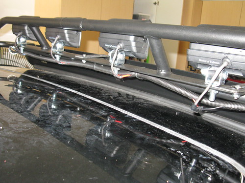
For this install I cannibalized the wiring harness that came with the lights. You do need to buy 40ft of 12 gauge (stranded; NOT solid core) to run power from the engine bay to the rear of the roof.

5931606389_fa3d2ff158_b.jpg

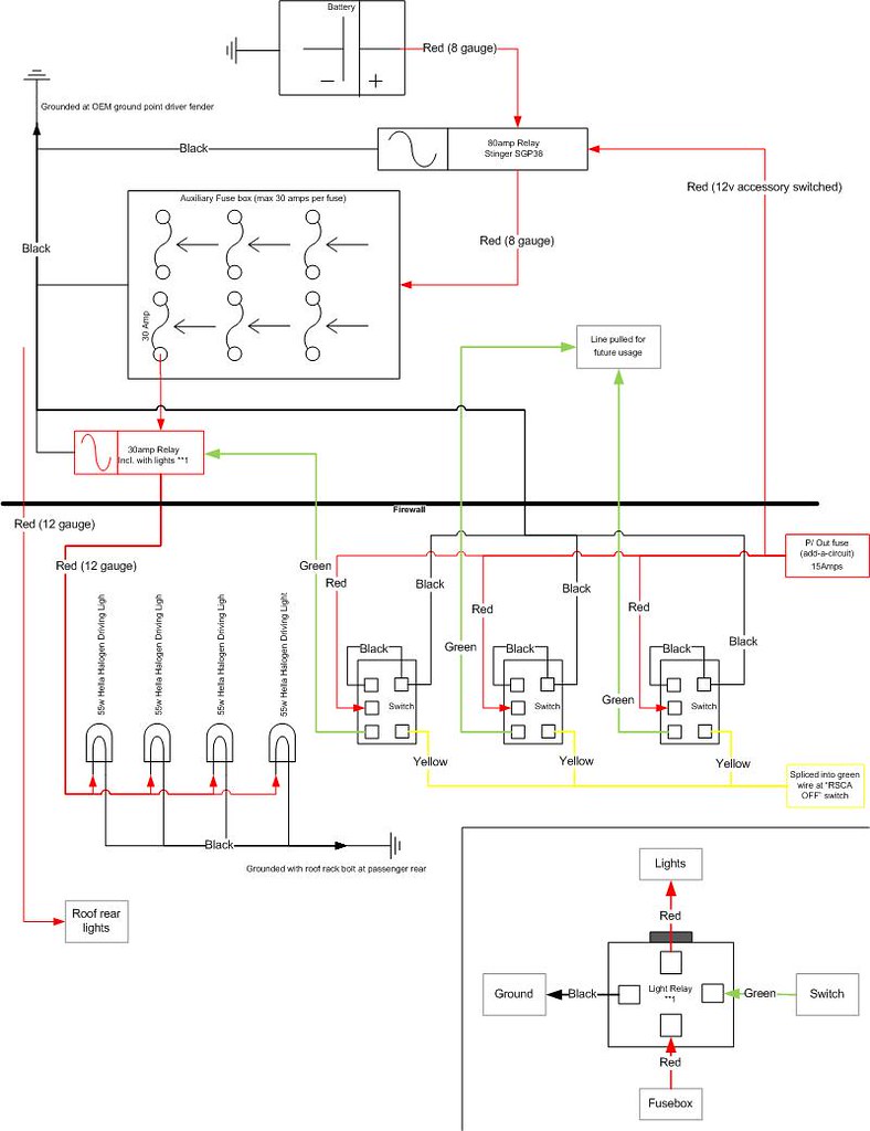
The electrical schema. I ordered 2 sets of HELLA 007133831 Micro FF Series 12V/55W Halogen Driving Lamp Kit
They were $55/each here: Amazon.com: HELLA 007133831 Micro FF Series 12V/55W Halogen Driving Lamp Kit: Automotive

For details on the switches and fusebox, please see my Auxiliary Fuse Box write up.

5968250355_afa39ba8af.jpg


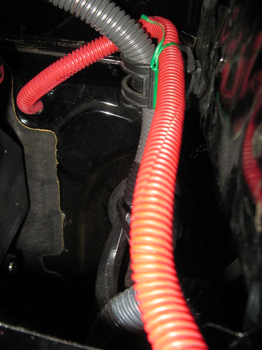
FROM THE ENGINE BAY TO THE ROOF:
5968246119_843369ec68.jpg

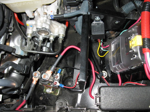
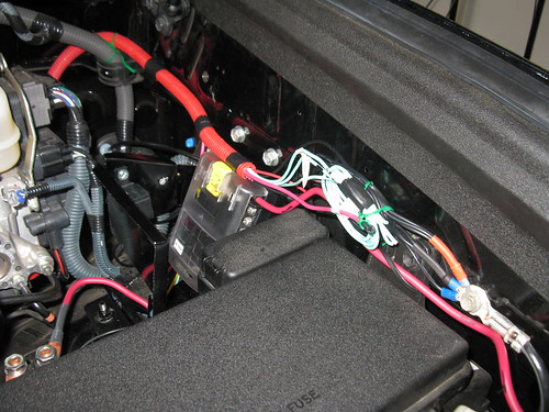
Fusebox (high voltage relay switched) and relay for lights. I fabricated the brackets for the fusebox and the relay from sheet aluminum. The Stinger SGP38 relay is mounted using factory threaded holes in the fender. My brackets also use factory holes.

5968245285_beb0fa3fe2.jpg

Grounded on factory grounding

5931616933_3fb2a552ab.jpg

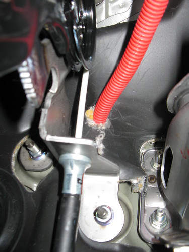
Routed via existing hole in firewall into the cab.

5932173518_a745b13696.jpg

Hole cut into rubber to allow wires through (left side driver foot-well)

6003514439_470d027103.jpg
6004062310_7f146a315f.jpg

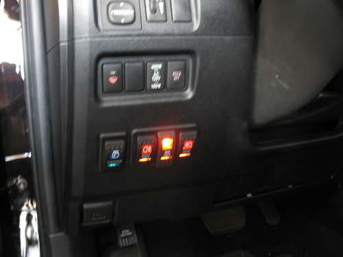
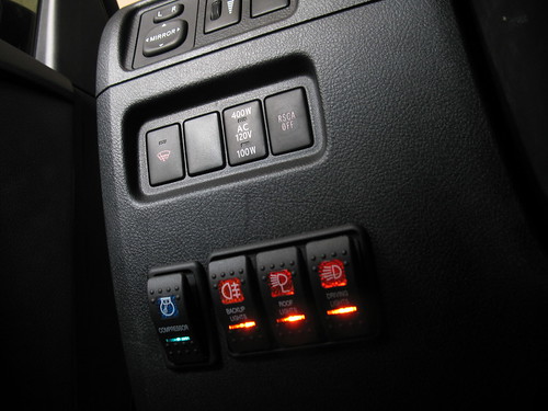
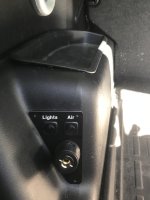
Trim a hole for your switches. What it looks like with switches installed.

5985791847_8f6943845f.jpg

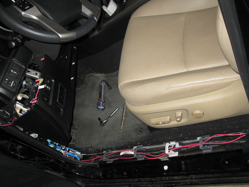
I used two 20ft wires to run from the engine bay to the rear roof. Pull the sill plates to hide the wire (driver side).

5986351224_3b1a08f9a8.jpg

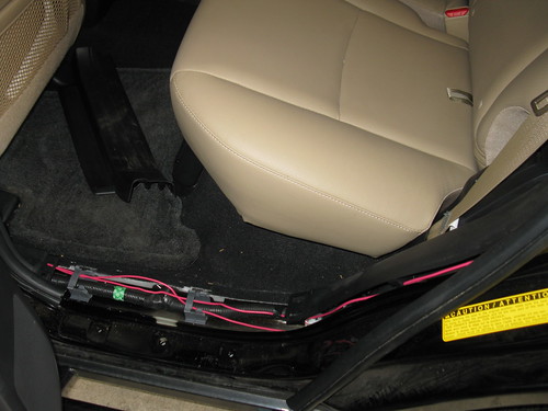
Pull sill plate for driver side passenger. Also pull the weather stripping to run the wires up into the cargo area.

5985790547_3cf2300e67.jpg

Fish the wires out of the jack cover.

5968790126_bf6ccef8ae.jpg

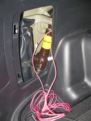
Run the wire up via the rear light access panel.

5968790630_0892840e07.jpg

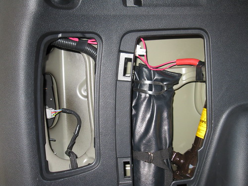
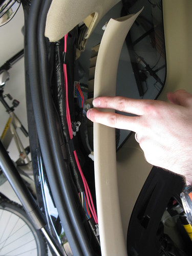
Pull the rear trim loose (does not need to be removed). this is the annoying part to run the wires through.

5968234187_0be6e569bc.jpg

5968791592_3166a31d06.jpg

Use a trim removal tool to pull the plugs from the headliner and carefully pull it down a bit while you run the wires into the light gate connection.

5968236511_b5beced607.jpg

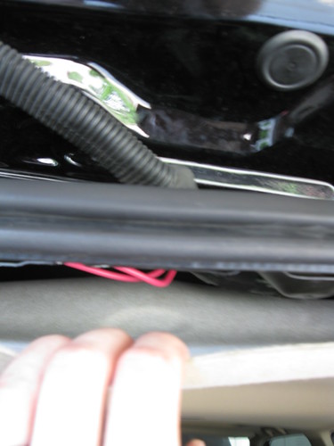
Trim a hole in the rubber and exit the wires. dont forget to wirewrap them. Run them under the rubber raingutter cover. You will have to trim a corner out.

5968235927_1d4164167a.jpg

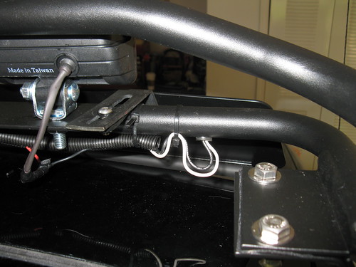
Run the wires under the rear mounting point for the rack and up to connect to the wires exiting from the rack (again.. wrap after connecting them). I used both white and black to run power to the lights. white powers 2 and black powers 2). both black and white are connected to a single powerline into the cab. the line for the rear lights is taped off for future usage.

5931618913_91dc8149fb.jpg

Wires cleaned up under the front of the rack.

5932175452_c5d44ddc36.jpg

The black and white wire on the passenger side of the rack are both use for grounding. each wire grounds 2 lights.

5931616273_5a5257d43c.jpg

Grounded via the rack bolts and covered with liquid electrical tape.

Click here to see the lights in action.


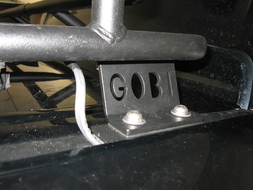
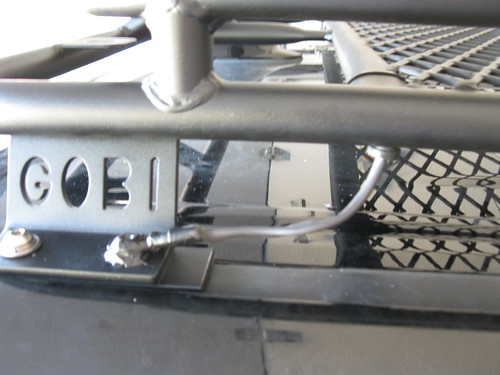
How in the world did you route your cable through the Gobi? I have grommets but it's very, very tight to get anything fished through there. Thoughts?
 
How in the world did you route your cable through the Gobi? I have grommets but it's very, very tight to get anything fished through there. Thoughts?

The Gobi has wires usually already ran through it. If you pull the grommet, you should see the wire and you can pull the ends. Just don't pull to hard like I did and pull the entire wire out. I ended up using one of the wires as a way to fish new wires through.
 
How in the world did you route your cable through the Gobi? I have grommets but it's very, very tight to get anything fished through there. Thoughts?

The Gobi has wires usually already ran through it. If you pull the grommet, you should see the wire and you can pull the ends. Just don't pull to hard like I did and pull the entire wire out. I ended up using one of the wires as a way to fish new wires through.

What [MENTION=102185]WODWorldWide[/MENTION] said... mine came prewired.

Okki
 
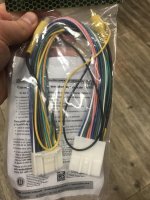
Hey quick question, is this the style of harness you used to tie in an aftermarket camera to the factory head unit? Seems a little overkill to me so thought I'd check. Thanks!
 

Attachments

  • IMG_6302.jpg
    IMG_6302.jpg
    131.5 KB · Views: 1,264
Hey quick question, is this the style of harness you used to tie in an aftermarket camera to the factory head unit? Seems a little overkill to me so thought I'd check. Thanks!

Seems I missed this post for quite a while. This is the harness that I used.
AX-TOYCAM2 Toyota Back-Up Camera Retain/Add-On METRA AX-TOYCAM2

Keep in mind that you need to wire both power and ground via this harness for the head unit to switch to the video signal when in reverse. That also means that you need a 6 volt compatible camera. I don't know if on the later models Toyota switched back to 12 volt cams, but the 2010 uses a 6 volt cam.

Okki
 
Seems I missed this post for quite a while. This is the harness that I used.
AX-TOYCAM2 Toyota Back-Up Camera Retain/Add-On METRA AX-TOYCAM2

Keep in mind that you need to wire both power and ground via this harness for the head unit to switch to the video signal when in reverse. That also means that you need a 6 volt compatible camera. I don't know if on the later models Toyota switched back to 12 volt cams, but the 2010 uses a 6 volt cam.

Okki

Got it, thanks for getting back to me.
 
Icon Vehicle Dynamics Billet Upper Trailing Arms Maintenance

Icon Vehicle Dynamics Billet Trailing Arms – 2010+ Toyota 4Runner

Damaged Bushings:
The image below shows a broken load-ring with a chunk broken out of it as well. The bushing sleeve is also extremely corroded due to lack of maintenance and harsh weather exposure. This is a serviceable part and not a manufacturing issue.
37930300664_691e67ece1_c.jpg


Tools Needed
Icon Trailing Arms:
19MM Socket
21MM Socket
24MM Socket
Socket Breaker Bar
Socket handle extension (Jack handle?)
Rubber Mallet
Grease Gun
Zerk Straight Fitting
12 ton Jack Stands
Hi-Lift
3/8 Wrench
3/8” 12PT SOCKET / WRENCH
(Borrow from Auto-Zone) Bushing Press

Upper Arm Torque 59ft-lbs
Lower Arm Torque 96ft-lbs


WHY:
Just like any other moving part on your truck, your trailing arms need regular maintenance. In order to keep your (costly) investment in your aftermarket suspension in the best possible shape, it’s recommened your perform the following maintenance twice a year. Please keep in mind that overdoing the grease pumping into your bushing may cause hydrolic pressure that can disform the bushing and cause damage due to misalignment to your trailing arms.

If you notice damage/cracking on the ears of the bushings, replace them. The “ears” are the wider part of the (red) bushing in the image below.

38726900654_334f7e704f_o.jpg


WARNING:
Using a properly rated jack, raise the rear of the vehicle and support the frame rails with jack stands. Ensure the jack stands are secure and set properly before lowering the jack. NEVER WORK UNDER AN UNSUPPORTED VEHICLE.

INSTALLATION:
Jack the vehicle and set on jack stands with the rear wheels off the ground.
!!! Remove one link at a time!!!

Upper Trailing Arm
Maintenance Greasing:
1. At the frame side; Undo the bolt (don’t remove) to reduce tension on the bushing and allow releave from the grease if needed. You do not need to remove the bolt, but allow some space to be created between the nut and the frame.
2. Using the straight fitting on your grease gun, pump grease slowly into the bushing. Stop as soon as you feel the pressure increase, or you see grease pushing out of the ears.
3. Retorque the bolt back to 59ft-lbs.
4. No grease should be applied on the rod-end (axel). This will attract debris that increases wear and can cause damage to the ball/sleeve.

Replacing Bushings:
!!! Remove one link at a time!!!
1. At the frame side; Undo the bolt and remove from the sleeve. Set aside in a tray/container for later reuse.
2. Using the rubber mallet/dead-blow hammer, tab the upper trailing arms out of the bracket on the frame.
3. At the axle side; Undo the bolt and remove from the sleeve. Set aside in a tray/container for later reuse.
4. Remove the Upper Trailing Arm from the vehicle.
5. Remove bushings. If there is damage to the bushing sleeve, you may need a bearing press to push the center sleeve out.
24775539498_c8e2c65c5b_c.jpg
24775539808_43d6851767_c.jpg

6. Once the center sleeve has been removed, you can fairly easily pull the polyurethena bushing.
7. Clean out the inside of the bushing housing.
38615652712_6c9db3e096_c.jpg

8. Check that the zerk fitting is tightened all the way down. Failure to have it down to the bushing housing may result in reduced headspace between the zerk fitting and the frame. This may result in the zerk fitting being pulled from the trailing arms and causing damage.
9. Care must be taken to grease the bushings (liberally) prior to installing assembly. Failure to grease properly will cause premature bushing wear and increased noise.
38647858141_e1617a84cb_c.jpg

10. Apply grease to one bushing and the center sleeve. Align the load ring in the center.
38615649502_536b87e007_c.jpg

11. As you push the center sleeve and loadring into the housing, the loadring may shift. You can make a simple tool to ensure the loadring is properly positioned in the center of the assembly (see pictures below).
12. Once the loadring is properly adjusted, apply some grease to the exposed side and grease up the second bushing.
38647855171_6d7ef7d84f_c.jpg

13. Reinstall bushings.
38647857611_9078a0f458_c.jpg

14. Install the axel-side of the upper trailing arm.
15. Insert the bolt and finger tighten the nut.
16. Install the frame-side of the upper trailing arm (this may need some gentle taps from the mallet).
17. Insert the bolt and finger tighten the nut.
18. Check that everything aligns
19. Retorque the bolt back to 59ft-lbs (2010+ 4Runner).
20. VERIFY ALL FASTENERS ARE PROPERLY TORQUED BEFORE DRIVING VEHICLE. RETORQUE ALL NUTS, BOLTS AND LUGS AFTER 100 MILES AND PERIODICALLY THEREAFTER.

24568700117_6e708f6bea_o.jpg

Both bolts need to be torque to 59 ft-Lbs


LOAD RING TOOL:
37930303304_e363607607_c.jpg

26872027669_c05f7337ca_c.jpg

Use a marker to indicate where your alignment slot needs to be. Use a saw to cut a relief so you can see when the loadring is pushed down to the appropriate depth.
38591927286_1168663a1d_c.jpg

Press the load-ring down until the edge of the bushling sleeve is visible through the alignment-slot.

38647855171_6d7ef7d84f_c.jpg
 
Last edited:
Selling my first ascent katabatic tent

Selling my First Ascent Katabatic 4 Season tent. For details please see the "for Sale" Section.
http://www.toyota-4runner.org/sale-...sale-lots-extras-$550-carmel.html#post2931294

My attention deficit disorder and "ohh shiney! I want it!" will be someone's great deal on a great tent that has 5 days of use on it!!!

Great starter deal for someone getting into ground camping, or a family where the kids are big enough for their own tent to set up beside mom and dad.

Thanks and have a great day!
Okki
 
Rear Differential Breather Relocation to Engine Bay


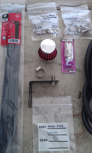
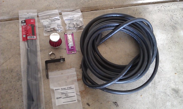
Item Description Quantity Unit Price Total Cost Vendor

90404-51319Rear Diff Union1 $ 7.50 $ 7.50 toyotatrdpart.com

270703/8 Fuel hose14ft $ 1.49 $ 22.32 O’Reillys

3992Breather Filter Red/Chrome1 $ 9.99 $ 10.69 O’Reillys

3/8 Hose clamp2 $ 1.07 $ 2.29 Lowes

47307Vacume Connection kit1 $ 3.99 $ 4.27 O’Reillys

Total $ 47.07


Per [MENTION=117301]T4Rdvm[/MENTION], the bolts that fit in the OEM threaded holes in the engine bay are: M8-1.25 bolts. The recommendation is M8-1.25x20 stainless.


So in preparation for my trip to the FJ Summit I completed the rear differential breather modification. This is basically moving the breather end-point to a higher point on the vehicle in order to prevent the inadvertent intake of water into the differential when fording or doing a river crossing.


With the exception of the bracket, I made that myself out of some stock aluminum I had gotten from Lowes, all the parts for this project can be had for under $50.

7192169566_072bb6e4f2_z.jpg


I ordered the rear differential union from toyotatrdpart.com. They offer great service and the best deal on this OEM Toyota part.


7192323344_1ea6b4899a_z.jpg


What did you use the "47307 Vacum Connection kit" for?

Edit, just noticed the filter has a female end. Makes sense that you would need a barrel to join the hose.
 
Last edited:
Air Chuck and Controls in Cargo Area

Great write up of your Pressure Gauge and Air Chuck in the cargo area! I use my compressor not only for filling up the tires after some wheeling, but for bike maintenance as well. I used your write up (and diagram) to place an air chuck in the rear and a switch to activate the compressor and a NC valve in the front to shunt air to the rear. I haven't started my own build thread yet, but want to thank you for the detail in yours! I placed the valve next to the air compressor so that if something ever did happen to the line while I am out on the trail, I still have the chuck attached directly to the air compressor and no loss of air. I ran the control wires on the same path as the air hose, using 16 gauge marine wire, wrapped in marine grade heat shrink, and using a semi-rigid plastic split loom.

Air Valve: Vixin Air 3/8 NPT (I picked this one as it's rated for high pressure and high flow. I went a size up and used reducers on both ends to get it back down to 1/4 NPT, wanting to minimize loss of flow.
 

Attachments

  • RearCargoArea.jpg
    RearCargoArea.jpg
    135.4 KB · Views: 1,173
Water Rotopax Disinfection

Rotopax: https://rotopax.com/rotopax/water-packs/
Sanitation Source: https://www.cdc.gov/healthywater/emergency/drinking/cleaning-preparing-storage-containers.html

Before filling with safe water, use these steps to clean and sanitize water storage containers:

  1. Wash the storage container with dishwashing soap and water and rinse completely with clean water.
  2. Sanitize the container with a solution made by mixing 1 teaspoon of unscented liquid household chlorine bleach in one quart of water.
  3. Cover the container and shake it well so that the sanitizing bleach solution touches all inside surfaces of the container.
  4. Wait at least 30 seconds and then pour the sanitizing solution out of the container.
  5. Let the empty sanitized container air-dry before use OR rinse the empty container with clean, safe water that is available already.

Keep in mind:
  • Replace stored water every six months.
  • Keep stored water in a place with a fairly constant cool temperature (50-70° F).
  • Do not store water containers in direct sunlight.
  • Do not store water containers in areas where toxic substances, such as gasoline or pesticides, are present.
 
Last edited:
2012 ltd build to off road

Okki -

Really appreciate your build thread. I've got a 2012 Limited and want to move toward more of an off road look and performance. I want to start with 17" wheels and much more aggressive tires. Do you anticipate any issues with the XREAS suspension system when I go to the more TRD type tires and wheels? I don't have the $$ for a suspension lift at this time. Thanks. Also, if you can share any photos of your finished 4Runner that would be great.
 

Members online

Forum statistics

Threads
278,309
Messages
3,554,068
Members
248,016
Latest member
Advally Service

Trending content

Back
Top