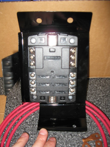
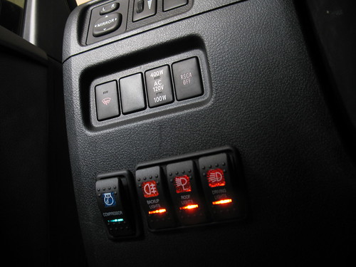
I mounted an auxiliary fuse box to power the roof lights that I have on my Gobi Stealth Rack, but also so that I would have everything in place for any additional lights I may want to mount and a compressor.
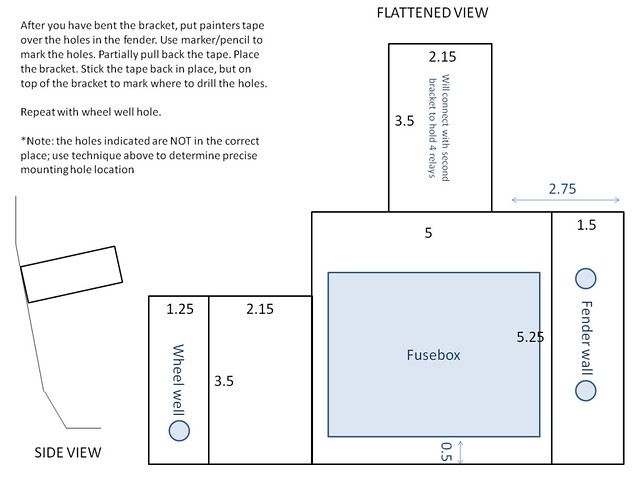
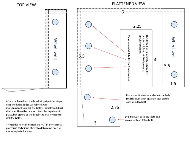
Lets start with the boring stuff. Below are the electrical schematics and the drawings for the brackets I fabricated.
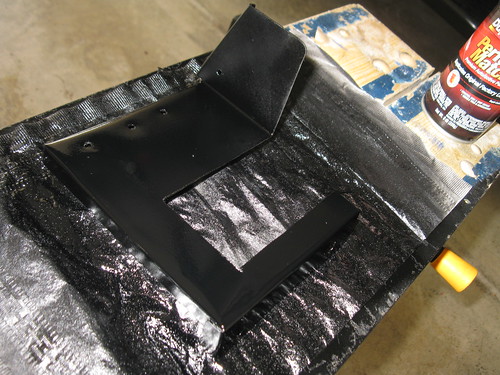
Fuse Box Bracket:
Relay Bracket:
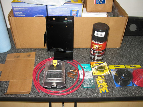
I fabricated the brackets out of sheet aluminum that I picked up at Lowes.
I ordered all the surrounds and switches from
Over The River And Throw The Woods (
www.otrattw.com):
Product ID: V1D1J66B-AFCN5-17U
Product Name: V-Series Contura II sealed rocker switch, Driving Lights
Quantity: 1
Unit Price: $12.00
--------------------------
Product ID: V1D1J66B-AYC9A-CP1
Product Name: V-series Contura II sealed rocker switch, Compressor
Quantity: 1
Unit Price: $12.00
--------------------------
Product ID: V1D1J66B-AFCM4-RF1
Product Name: V-Series Contura II sealed rocker switch, Roof Lights
Quantity: 1
Unit Price: $12.30
--------------------------
Product ID: V1D1J66B-AFC77-18B
Product Name: V-Series Contura II sealed rocker switch, Backup Lights
Quantity: 1
Unit Price: $12.30
--------------------------
Product ID: VMS-01
Product Name: Snap-In Single Switch Holder
Quantity: 1
Unit Price: $1.75
--------------------------
Product ID: VM3-01
Product Name: Snap-In Three Position Switch Holder
Quantity: 1
Unit Price: $5.30
--------------------------
Product ID: 5025B
Product Name: Blue Seas ST Blade Fuse Block With Cover
Quantity: 1
Unit Price: $27.95
--------------------------
Please not that these switches DO NOT FIT IN THE OEM SLOTS! You need to enlarge the locations (taller) or cut a big hole and use the snap in panel like I did.
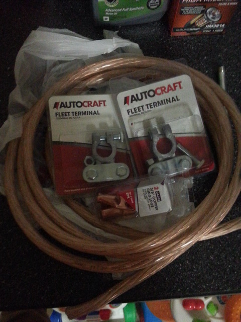
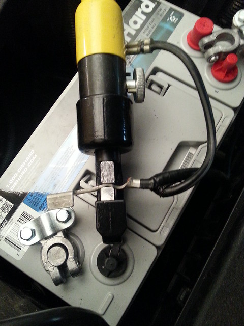
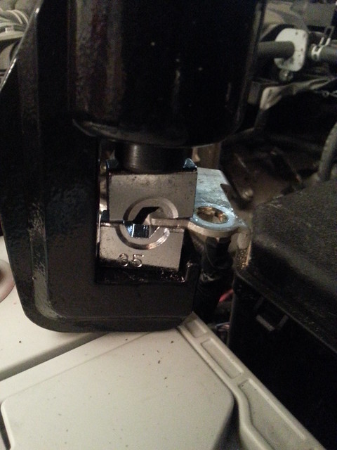
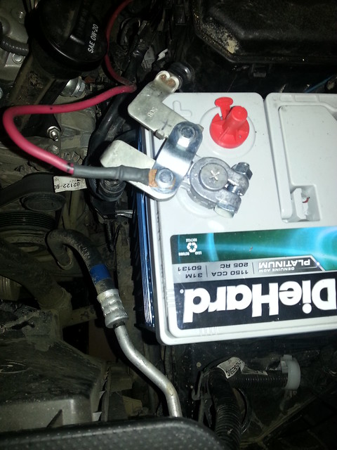
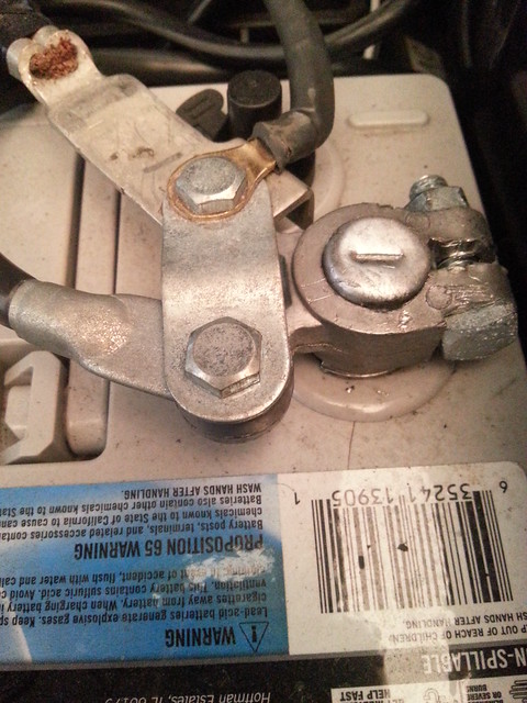
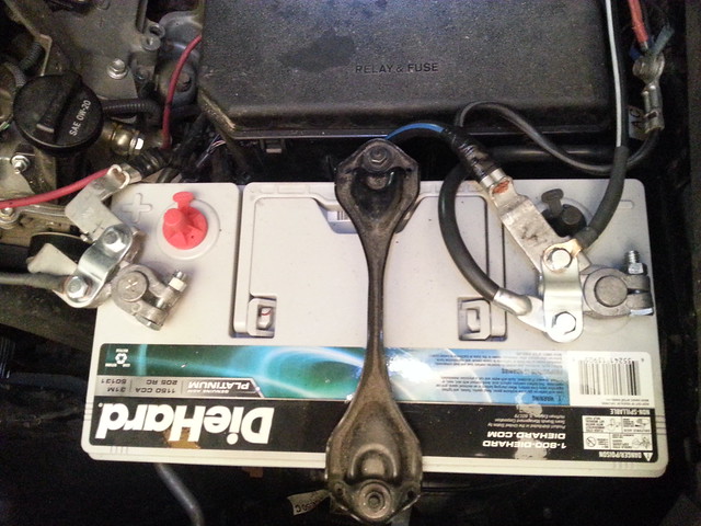
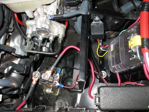
The fusebox is connected to the battery using 8 gauge stranded wire. On the battery side you can use 8 gauge copper lugs, but on the high-voltage relay side I had to use 6 gauge lugs because I needed a 3/8 hole. I cut a T-shape in the top of the lug so I could properly compress the lug around the wire.
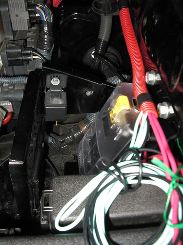
Make sure you leave enough room on either side of the brackets so you have room for the terminals to come off the fuse box.
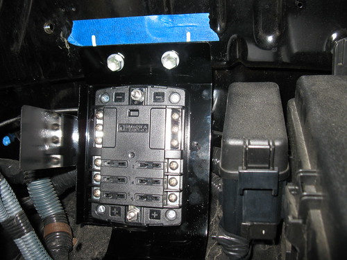
On the fender wall you can use existing threaded holes to secure the bracket. When you have the bracket bent in the right shape, place 2 pieces of painters tape on the fender wall, one covering each hole. mark the hole on the take with pencil. Pull back partially, place the bracket and stick the tape back. remove the bracket with the tape in place and drill the mounting holes accordingly.
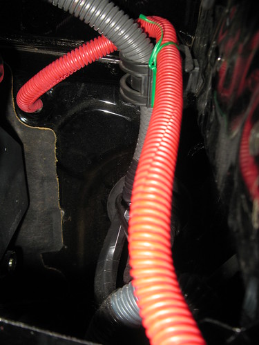
I used an existing hole in the firewall to run cable guide and wires.
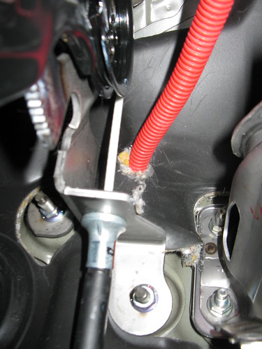
I used a hobby knife to cut through the insulation and rubber backing that is inside the driver footwell. I started the cutting from the engine bay so you know the exact location to trim your hole.
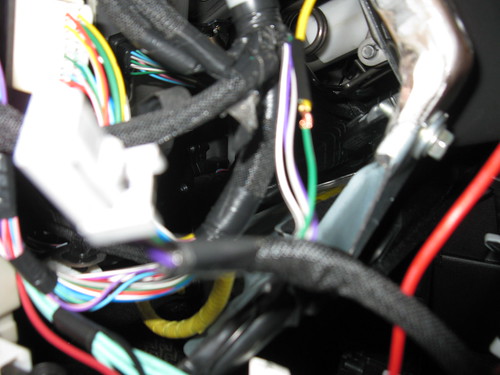
This is the view inside the driver foot well;
I have a total of 8 wires running through this passage.
A second bracket provides a mounting spot for an additional 3 relays (or other items) and reinforces the fusebox bracket.
In the final installation I used Allen bolts.
To the left of the bracket you can see the Stinger SGP38 High Voltage relay. It was mounted using two threaded holes that already existed in the wheel well. they are shallow holes, but provide enough threads to hold the relay securely in place.
As mentioned, I needed to modify 2 6 gauge copper lugs with 3/8 hole in order to connect to the terminals on the relay.
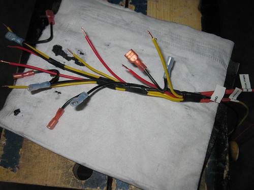
I fabricated a wiring harness from the harness that came with my Hella lights, but any 16 or 18 gauge wire will do.
Black = ground
Yellow = Dashboard light; spliced into RSCA switch green wire
Red = 12 volt accessory switched; use add-a-circuit on P/Outlet mini fuse or splice into appropriate wire.
Green (not shown) = Switch to relay
Hook up the switches and you are good to go!