I did a lot of searching and found stuff scattered around in different threads. I wanted to post my experience in hopes that it helps others who have similar issues and are looking for how to accomplish the replacement and bleed the brakes without needing Techstream. Disclaimer: YMMV.
Background:
I purchased an '05 SR5 V6 a couple months ago to act as a third vehicle for my wife and teenagers to drive. I didn't want them driving my '99 Land Cruiser everywhere, risking it getting wrecked. A 4Runner would be a lot easier to replace than my beloved 100-series. The 4Runner had good maintenance history and ran well. I decided to purchase it without doing a thorough pre-purchase inspection. Don't make the same mistake I did!
Within a day of it becoming mine, I started noticing a 'thunk' sound coming from the driver-side firewall and could hear a motor running immediately after the 'thunk'. This would happen every 10 seconds, and last for a couple seconds. I didn't matter if the vehicle was running, just the key on, driving down the road, brake pedal depressed, etc. I eventually diagnosed this as the accumulator not holding pressure. Rather than shelling out $2k - $4k to have Toyota fix the vehicle I just purchased for $6,500, I decided to fix it myself, like I do with just about everything.
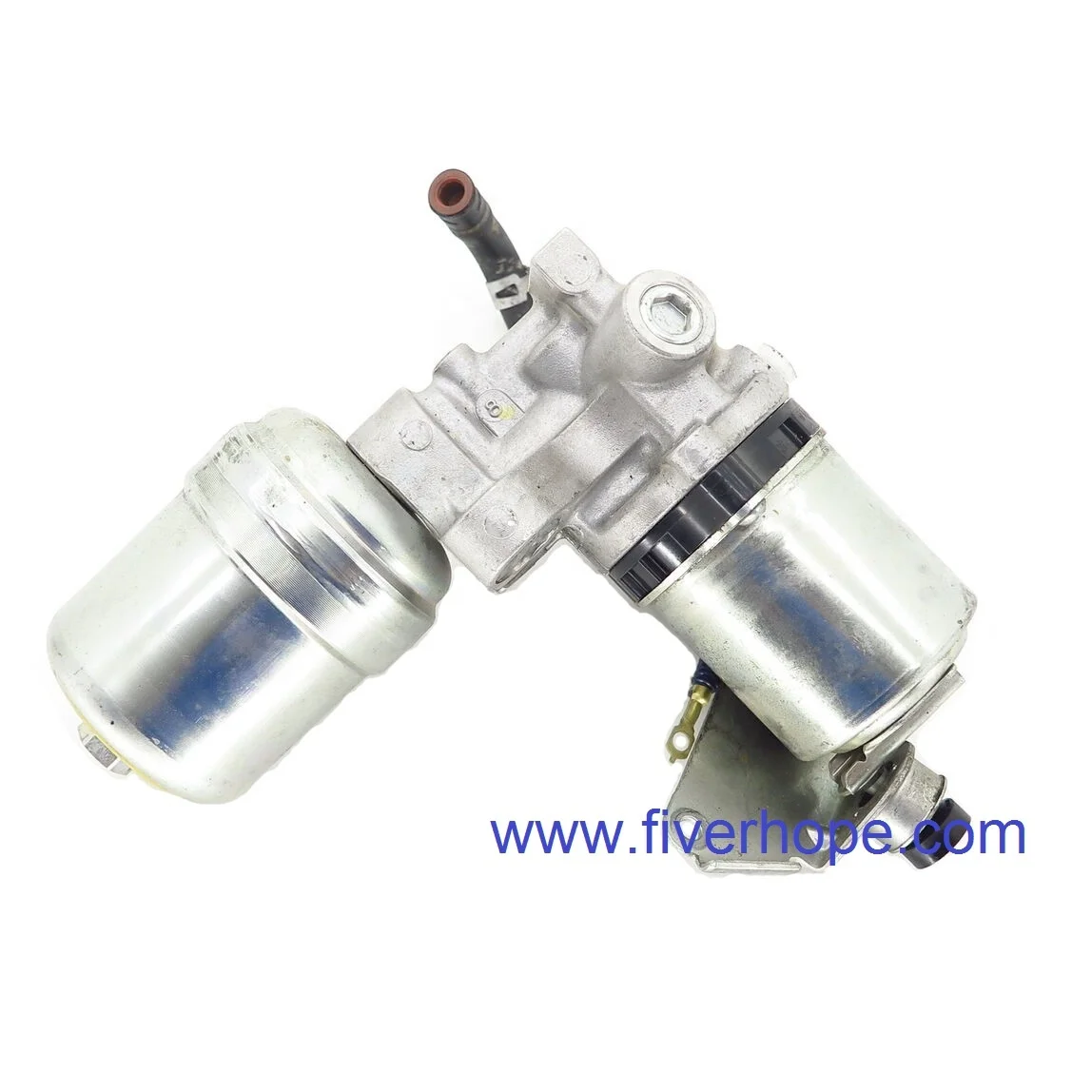
After reading lots of threads about similar problems and hooking it up to Techstream to confirm that the accumulator pressure was not holding steady like it should be, I decided the best route to fix this would be to replace the accumulator and pump/motor assembly. My local Toyota dealer wanted $700 for this assembly. I decided I'd prefer to find used parts to save money. I got a complete brake master assembly from a salvage yard in San Diego for $300 (off Ebay). They claimed this unit came out of a 2010 (5th gen) with 70K miles. I would like to note that the part number on the side of the ECU cover differed by one number from the unit on my 4th gen. But because I was only replacing the pump and accumulator, I didn't care about the ECU # being different.
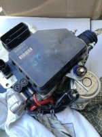
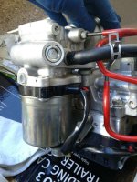
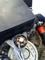
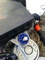
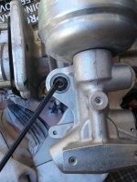
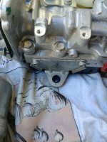
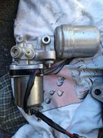
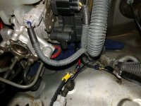
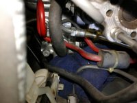
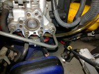
I had seen some folks ask if it is possible to replace the accumulator and pump assembly without removing the entire master cylinder assembly. I can confirm this is possible because I did it. It was not easy. It may have been faster to just remove the whole unit from the firewall and swap out the parts. But I didn't want to introduce any additional air into the lines and I didn't want to just swap out the entire assembly because I suspected I would need to calibrate the new brake ECU to work on my vehicle. I just wanted to remove the parts I suspected had failed and minimize the chance of air getting into the system. It required a lot of patience, lots of dexterity in my fingers and lots of pain in my hands and lower back. The motor and pump are attached to the unit through 3 rubber mounts. Two come off easily (side of pump). One was difficult (end of motor housing) because it used a metal ring retainer that I basically had to pry off and then straighten back out with some pliers before using it again later.
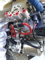
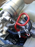
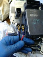
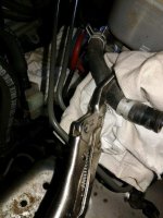
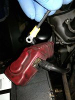
Another key thing I did was to manually purge the air out of the pump and accumulator by disconnecting the high pressure line where it connects to the side of the master cylinder and then running the leads directly to the battery. What this allowed me to do was bleed most of the air out of the pump and accumulator, flushing out old fluid and not involving pushing air through the master cylinder and out to the wheel ends. I attached a clear vinyl tube to the end of the high pressure line and then ran the other end of the tube into an empty quart oil bottle to catch all the fluid being pumped through it. I would pump a little, then let things settle for a minute, then repeat. The final resting to try to get bubbles to settle was about 10 minutes before the final purge of new fluid and bubbles. Once I had pumped a few cups of fluid, I reconnected the high pressure line to the side of the master cylinder. Full warning, threading the flare nut back into its proper location is very difficult and requires a lot of patience. There is a little preload on the high pressure line that causes it to not line up perfectly. It took a while to get it back on there. Another warning, make sure you use a 'line wrench' for flare nuts. If you use standard open-end wrenches, you will round off the flats on the flare nut and destroy them. I got a set of metric 'line wrenches' from Harbor Freight.
The last step in the process was to bleed the brakes. I was worried this wouldn't work very will without Techstream. It actually went just fine. I used the instructions posted on this thread in post #3 and followed the procedure for bleeding the accumulator, front brakes and rear brakes:
http://www.toyota-4runner.org/4th-gen-t4rs/145716-brake-bleeding-w-abs-w-o-sst-tool.html
I bled about 6 oz from the front calipers before getting a little air and clean fluid and maybe 12 oz out from the rear calipers with the same results.
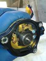
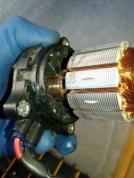
Ultimately, there wasn't much air bubbles that came out that I noticed so I think my pre-purge of the accumulator was helpful. I will post some photos right after this to show various setups and details. If you've got specific questions, I can try to answer them. I just don't have the time to do a step-by-step how-to of the process.
Background:
I purchased an '05 SR5 V6 a couple months ago to act as a third vehicle for my wife and teenagers to drive. I didn't want them driving my '99 Land Cruiser everywhere, risking it getting wrecked. A 4Runner would be a lot easier to replace than my beloved 100-series. The 4Runner had good maintenance history and ran well. I decided to purchase it without doing a thorough pre-purchase inspection. Don't make the same mistake I did!
Within a day of it becoming mine, I started noticing a 'thunk' sound coming from the driver-side firewall and could hear a motor running immediately after the 'thunk'. This would happen every 10 seconds, and last for a couple seconds. I didn't matter if the vehicle was running, just the key on, driving down the road, brake pedal depressed, etc. I eventually diagnosed this as the accumulator not holding pressure. Rather than shelling out $2k - $4k to have Toyota fix the vehicle I just purchased for $6,500, I decided to fix it myself, like I do with just about everything.
After reading lots of threads about similar problems and hooking it up to Techstream to confirm that the accumulator pressure was not holding steady like it should be, I decided the best route to fix this would be to replace the accumulator and pump/motor assembly. My local Toyota dealer wanted $700 for this assembly. I decided I'd prefer to find used parts to save money. I got a complete brake master assembly from a salvage yard in San Diego for $300 (off Ebay). They claimed this unit came out of a 2010 (5th gen) with 70K miles. I would like to note that the part number on the side of the ECU cover differed by one number from the unit on my 4th gen. But because I was only replacing the pump and accumulator, I didn't care about the ECU # being different.
I had seen some folks ask if it is possible to replace the accumulator and pump assembly without removing the entire master cylinder assembly. I can confirm this is possible because I did it. It was not easy. It may have been faster to just remove the whole unit from the firewall and swap out the parts. But I didn't want to introduce any additional air into the lines and I didn't want to just swap out the entire assembly because I suspected I would need to calibrate the new brake ECU to work on my vehicle. I just wanted to remove the parts I suspected had failed and minimize the chance of air getting into the system. It required a lot of patience, lots of dexterity in my fingers and lots of pain in my hands and lower back. The motor and pump are attached to the unit through 3 rubber mounts. Two come off easily (side of pump). One was difficult (end of motor housing) because it used a metal ring retainer that I basically had to pry off and then straighten back out with some pliers before using it again later.
Another key thing I did was to manually purge the air out of the pump and accumulator by disconnecting the high pressure line where it connects to the side of the master cylinder and then running the leads directly to the battery. What this allowed me to do was bleed most of the air out of the pump and accumulator, flushing out old fluid and not involving pushing air through the master cylinder and out to the wheel ends. I attached a clear vinyl tube to the end of the high pressure line and then ran the other end of the tube into an empty quart oil bottle to catch all the fluid being pumped through it. I would pump a little, then let things settle for a minute, then repeat. The final resting to try to get bubbles to settle was about 10 minutes before the final purge of new fluid and bubbles. Once I had pumped a few cups of fluid, I reconnected the high pressure line to the side of the master cylinder. Full warning, threading the flare nut back into its proper location is very difficult and requires a lot of patience. There is a little preload on the high pressure line that causes it to not line up perfectly. It took a while to get it back on there. Another warning, make sure you use a 'line wrench' for flare nuts. If you use standard open-end wrenches, you will round off the flats on the flare nut and destroy them. I got a set of metric 'line wrenches' from Harbor Freight.
The last step in the process was to bleed the brakes. I was worried this wouldn't work very will without Techstream. It actually went just fine. I used the instructions posted on this thread in post #3 and followed the procedure for bleeding the accumulator, front brakes and rear brakes:
http://www.toyota-4runner.org/4th-gen-t4rs/145716-brake-bleeding-w-abs-w-o-sst-tool.html
I bled about 6 oz from the front calipers before getting a little air and clean fluid and maybe 12 oz out from the rear calipers with the same results.
Ultimately, there wasn't much air bubbles that came out that I noticed so I think my pre-purge of the accumulator was helpful. I will post some photos right after this to show various setups and details. If you've got specific questions, I can try to answer them. I just don't have the time to do a step-by-step how-to of the process.
Last edited: