Wiring for heated seats and diagram for power seats

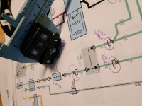
Anyone have a wiring diagram for the Power seats on our 4th Gens?

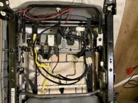
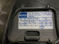
I have a 2008 SR5 and I’m wiring some heated seat pads that I put in. It has the 30A fuses ea. For driver and passenger seats in the interior fuse box. I recall reading something a while back where someone just used the power in the same fashion. Looking for a hot wire to tap into under the seat controlled by ignition. Thought I’d found one (Green). on the multimeter but wasn’t enough power when switched on, not seeing any others. If not, what pin on the back of the ECU and color would it be that would handle another 10.6A?

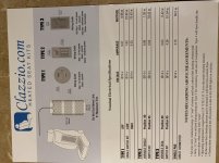
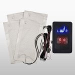
The kit only has a red (comes with a 7.5A inline fuse ea.) and black wire. Has a relay and is all plug and play other than power/ground. Clazzio kit with round switches. I don’t have any fuse taps and only lack wiring positive and want to get it done. I have done the full time power 12V mod for my cigarette lighters so can’t tie into that as I need to use an ignition wire.

If not I can extend the wires and run to the ECU if I need to. If so can someone post a pic and what pins to tie into? Says it needs at least 5.03A running ea. Seat (seat and back) for the heaters.

Clazzio Leather Seat Covers - Heated Seats Page
 

Attachments
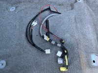
  • E045E3AF-0ACD-4FEE-8F9C-C98836D35AEA.jpg
    E045E3AF-0ACD-4FEE-8F9C-C98836D35AEA.jpg
    142.4 KB · Views: 7,689
  • 80999128-43B6-466E-8075-C2BC1ADFD83F.jpg
    80999128-43B6-466E-8075-C2BC1ADFD83F.jpg
    61.6 KB · Views: 9,797
  • 3C79D464-A9CA-4DCF-966C-7BEC85578F9A.jpg
    3C79D464-A9CA-4DCF-966C-7BEC85578F9A.jpg
    128.9 KB · Views: 7,261
  • D3B7814C-16D8-4CBC-95A4-045AF0BC2680.jpg
    D3B7814C-16D8-4CBC-95A4-045AF0BC2680.jpg
    134.3 KB · Views: 6,707
Last edited:
Register to hide this ad
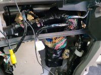
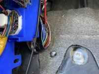
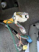
The heated seat wiring from the fuse box comes in through the driver's firewall and ends there by your left foot. If you wanted to run off the factory fuse you'd need to run wiring to that point. I followed this forum to do that with my Sport Edition.
 
Thank you guys for your responses! I wound up using the green wire in the driver kick panel that ties into the 25A fuse into the engine compartment labeled as seat heaters. Green wire ends at the IC4 and goes no further. Did the Relay swap from the Tow to the IG to give it power and have another relay on order to fill the tow spot.

Mission accomplished! :rockon:
 
Last edited:
Green wire ends at the IC4 and goes no further. ....

Mission accomplished! :rockon:

Were you able to confirm the LGreen wire does not reach the 3C harness connector, located at the center J/B (center console junction box) behind the a/c panel?

I noticed, what appears to be a LGreen wire there, which shows up on the wiring diagram for the seat heater. I would like to connect there, if that wire is the proper gauge, and for the seat heater.

I was able to snag a pic of the center j/b before I buttoned it back up after a stereo install. (07 Sport, (cloth seats)
 

Attachments

  • 20201226_145644 - R.jpg
    20201226_145644 - R.jpg
    127.6 KB · Views: 7,544
Great job. I am thinking about doing the same if I can not find the limited I am searching for. Good to know there are resources available for a DIY!
 
Were you able to confirm the LGreen wire does not reach the 3C harness connector, located at the center J/B (center console junction box) behind the a/c panel?

I noticed, what appears to be a LGreen wire there, which shows up on the wiring diagram for the seat heater. I would like to connect there, if that wire is the proper gauge, and for the seat heater.

I was able to snag a pic of the center j/b before I buttoned it back up after a stereo install. (07 Sport, (cloth seats)

I didn’t bother, I’d put enough time messing around as it was. I just put the relay in the IG spot, and checked for power and had it. Pulled the 25A fuse and no power verified. You could plan for that and check it that way. Worst case just run the wires a few more feet.
 

Attachments

  • 2745A0C3-2CC4-47E1-90DA-75284C4B6551.jpg
    2745A0C3-2CC4-47E1-90DA-75284C4B6551.jpg
    136.4 KB · Views: 6,573
Last edited:
The green wire behind A/C does not connect to the seat heater green wire at the left foot deriver's kick panel.

I was hoping maybe Toyota would have used any leftover Limited wiring on the non-Limiteds as the 4Gen was phasing out. :(

If my OCD kicks up, I may try to run a green wire to the junction box, as the diagram depicts.

I was able to source 2 pairs of NOS aftermarket 4 gen switches, waiting on the Limited center console trim piece, and the 07 Sport to return back in town for the install.
 

Attachments

  • 20210116_083443 _ r.jpg
    20210116_083443 _ r.jpg
    113.3 KB · Views: 8,871
I was hoping maybe Toyota would have used any leftover Limited wiring on the non-Limiteds as the 4Gen was phasing out. :(

If my OCD kicks up, I may try to run a green wire to the junction box, as the diagram depicts.

I was able to source 2 pairs of NOS aftermarket 4 gen switches, waiting on the Limited center console trim piece, and the 07 Sport to return back in town for the install.

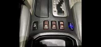
I hear you on the OCD, but limited patience for me and I was glad to just get it done myself. I wanted to go with the factory or factory looking switches too but I’d already bought a limited console that I’ve filled all 5 spots for.

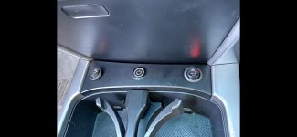
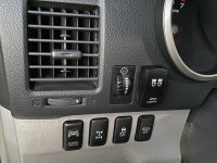
Limited realestate and couldn’t afford 2 more spots. Considered moving one and using the dual controls switch for 1 spot from Clazzio but decided to just use the small circular switches and use some free realestate. Looking at the rectangular Toyota switches from Clazzio now I don’t think it would fit proper into the console, possibly fit into one of the 2 dash spots with squared up corners?

Unfortunately I seem to run out of switch locations too fast and have 3 more currently I need to make room for that are hidden at kick panel.
 

Attachments

  • A57071A1-1192-4773-AA92-392E6E43DC3B.jpg
    A57071A1-1192-4773-AA92-392E6E43DC3B.jpg
    74 KB · Views: 6,475
  • 23B420FA-F5DB-4D6D-A4B4-9B344F20FAA3.jpeg
    23B420FA-F5DB-4D6D-A4B4-9B344F20FAA3.jpeg
    133.6 KB · Views: 7,003
  • 57D50F9E-3DFD-4206-A628-540E9C980F34.jpeg
    57D50F9E-3DFD-4206-A628-540E9C980F34.jpeg
    47.8 KB · Views: 6,225
  • DFA47B22-13BA-474D-9B2F-9862FE111337.jpg
    DFA47B22-13BA-474D-9B2F-9862FE111337.jpg
    136.4 KB · Views: 6,601
Last edited:
** Enter at your own Risk!!

{UNPLUG BATTERY Ground - wait 15+ mins., surf T4R.org}

The Seat Warmer Green Wire.... :whip:

Ends at the IC4 connector as mentioned by others... :high5:

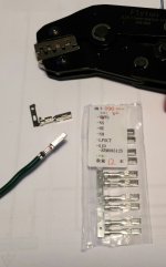
---> To add a female pin to the connector.

The IC4 connector consist of FOUR separate connectors, connected together.

IC4 needs to be unplugged, the specific connector unlocked, and removed from the cluster.

Once the connector is removed you can get to the lock on the connector to install the female pin.

{The blue, yellow, and gray connectors were removed to get to IC4}

Thanks to the T4R folks for the motivation.. :rockon:
 

Attachments

  • 20210318_201922 (1).jpg
    20210318_201922 (1).jpg
    70.8 KB · Views: 5,992
  • 20210318_205318.jpg
    20210318_205318.jpg
    133.5 KB · Views: 6,532
Last edited:

Members online

Forum statistics

Threads
278,317
Messages
3,554,125
Members
248,016
Latest member
Advally Service

Trending content

Back
Top