bergs
New member
I will continue to add pics and information as necessary/ requested.
This thread is to serve as a combination of what I learned as well as to provide very general guidelines on accessing the secondary air pump and control valve on affected 4.7L Toyota engines. Because of slight variances between the UZ engines I feel the need to specify that this work was performed on a 2UZ-FE VVTi engine.
It all began after my truck had sat for a week while I was away on business. Upon my return, the unmistakeable shop vac sound was heard upon startup. Somehow I was able to avoid engine codes for 3 days and in that time ordered the reliable AIP (Air Intake Pump) bypass supplied by our faithful member, slyfox75. Unbeknownst to me, this would end up as the beginning of an intimate relationship with what was about to take place....intake plenum removal and a deep understanding of how absurd this system is.
To the uninformed, the secondary air pump system does absolutely nothing other than inject oxygen into the exhaust manifold during cold starts which in turn satisfies EPA requirements. This means the same shitty emissions are still present and are nothing more than diluted for about 2 minutes during cold starts. This detail is important to know since the United States government allows such ridiculous "solutions" in an effort to achieve certain emissions numbers. I will save any further opinion on this matter. Just know this particular emission, at least at the time this was typed, is NOT tested in any state within the United States of America. Cold starts are not how emissions testing is performed and is only a requirement for manufacturers to follow. You will not be anal probed by black helicopters for bypassing this system.
:bored:
Okay....deeeeeeep breath.
To help with some questions, the air pump will be considered as the starting point in the system. Keep this in mind as you read on. It will help you understand some of the terminology I will be using words such as "up" or "behind" to describe parts locations or flow direction.
The facts as I experienced them:
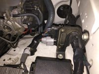
We are looking at the following parts in the picture...
25710 (air pump flow control valve) and 17600C (secondary air pump)

Please bear in mind that I had to make these repairs one day before flying out on business. That said, this will not be exactly picture heavy and you will need at least some level of mechanical aptitude in order to complete these repairs. This is written from the perspective that you have already removed everything up to the throttle body, have mechanical ability and understand certain safety requirements such as disconnecting the battery and bleeding off fuel pressure.
Tools needed to access the pump/ control valve:
Padding (mechanic's pad or similar)
Vacuum with crevice tool
Assortment of sockets ranging from 8mm to 17mm
Assortment of wrenches ranging from 10mm to 22mm
Mechanic's magnet
Pliers (needlenose, snubnose, etc, for removing hose clamps and retrieving dropped non-magnetic hardware)
Non-cholorinated brake cleaner
Paper towels
Total time: ~6h
Procedure:
Disconnect battery (assumed)
Vacuum everything around the intake plenum and engine block. Don't forget to vacuum around the injectors too!! Anything that is left behind runs the risk of falling into the engine and that can be bad.
Remove intake between airbox and throttle body (assumed)
Remove/disconnect all vacuum lines associated with the intake plenum
Trace all wire bundles around the intake plenum and loosen them from any retaining clips
Disconnect all injector electrical connectors and any other connectors within the work area
Remove the two 10mm bolts that secure the main wire harness to the rear of the intake plenum
Bleed off fuel pressure and remove fuel pressure regulator located on driver's side with a 22mm open end wrench. BE CAREFUL not to drop EITHER or BOTH washers on banjo bolt.
Disconnect and remove the hard fuel line located at the front, top of the intake plenum. Again, be careful to not drop the two washers required for each banjo bolt.
Loosen the 4 nuts and 6 bolts that secure the intake plenum and remove the hardware completely
Remove the rear most, passenger side banjo bolt located on the passenger side fuel rail. The hard fuel line can remain attached to the intake plenum
Loosen the four 10mm bolts that secure each fuel rail, in addition to the (what I will call) the secondary fuel pressure regulator located on the passenger side fuel rail
Lift one fuel rail at a time and pull injectors one-by-one ensuring there is no debris around the injector seals. I also recommend marking the location of each injector.
Removing the fuel rails is tricky however I discovered that if you slightly lift the plenum and rotate each fuel rail to a certain position, they will very easily slide forward and clear the engine hoist hooks that are in the way. I suppose you could remove both engine hoist hooks but I found removing the rails to be more straightforward.
Remove the intake plenum (!!!!!)
 arty:
arty:
You will see this:

Front and center is the secondary air pump. The next component is the control valve.
Remove both by loosening the hardware and rubber hoses. See next pic with air pump and control valve removed. Note the location of the starter near the top of the picture

Control valve disassembled with foam exposed:

Secondary air pump diassembled to show blower (note the few broken fins)

Clean the foam out of the control valve. After using compressed air and carefully scraping away the existing foam, I used non-chlorinated brake cleaner to spray inside the control valve body followed by drying it out with compressed air. Several attempts might be necessary. The key is to remove ALL of the foam as best you can.
It is strictly my opinion but I believe Toyota used the same foam to seal the air pump as was used inside the control valve. Look closely at the similarity in texture between the pics. The same sticky consistency was observed in material with both the control valve and secondary air pump seal.
NOTE: I cleaned all of the gasket surfaces with brake cleaner sprayed onto a paper towel. All of the intake plenum rubber was cleaned in the same manner, making sure there is a clean surface for the intake to seal to once it is installed to the engine block.
This thread is to serve as a combination of what I learned as well as to provide very general guidelines on accessing the secondary air pump and control valve on affected 4.7L Toyota engines. Because of slight variances between the UZ engines I feel the need to specify that this work was performed on a 2UZ-FE VVTi engine.
It all began after my truck had sat for a week while I was away on business. Upon my return, the unmistakeable shop vac sound was heard upon startup. Somehow I was able to avoid engine codes for 3 days and in that time ordered the reliable AIP (Air Intake Pump) bypass supplied by our faithful member, slyfox75. Unbeknownst to me, this would end up as the beginning of an intimate relationship with what was about to take place....intake plenum removal and a deep understanding of how absurd this system is.
To the uninformed, the secondary air pump system does absolutely nothing other than inject oxygen into the exhaust manifold during cold starts which in turn satisfies EPA requirements. This means the same shitty emissions are still present and are nothing more than diluted for about 2 minutes during cold starts. This detail is important to know since the United States government allows such ridiculous "solutions" in an effort to achieve certain emissions numbers. I will save any further opinion on this matter. Just know this particular emission, at least at the time this was typed, is NOT tested in any state within the United States of America. Cold starts are not how emissions testing is performed and is only a requirement for manufacturers to follow. You will not be anal probed by black helicopters for bypassing this system.
:bored:
Okay....deeeeeeep breath.
To help with some questions, the air pump will be considered as the starting point in the system. Keep this in mind as you read on. It will help you understand some of the terminology I will be using words such as "up" or "behind" to describe parts locations or flow direction.
The facts as I experienced them:
- Blockoff plates did not suit my application in that I would have broken a bunch of hardware
- The AIP bypass is not designed for a control valve that is stuck open (as in my case) and there is currently no way to get around this to my knowledge.
- Limp Mode indicates an open control valve. Exhaust pressure is being sensed behind the secondary valves
- The two secondary valves can easily be bypassed by blocking a couple vacuum lines and are hardly ever a point of failure
- If you happen to notice a sort of "airbox" noise, there is a chance the secondary valve is stuck open which means exhaust is making its way backwards through the system and possibly up to the pump
We are looking at the following parts in the picture...
25710 (air pump flow control valve) and 17600C (secondary air pump)
Please bear in mind that I had to make these repairs one day before flying out on business. That said, this will not be exactly picture heavy and you will need at least some level of mechanical aptitude in order to complete these repairs. This is written from the perspective that you have already removed everything up to the throttle body, have mechanical ability and understand certain safety requirements such as disconnecting the battery and bleeding off fuel pressure.
Tools needed to access the pump/ control valve:
Padding (mechanic's pad or similar)
Vacuum with crevice tool
Assortment of sockets ranging from 8mm to 17mm
Assortment of wrenches ranging from 10mm to 22mm
Mechanic's magnet
Pliers (needlenose, snubnose, etc, for removing hose clamps and retrieving dropped non-magnetic hardware)
Non-cholorinated brake cleaner
Paper towels
Total time: ~6h
Procedure:
Disconnect battery (assumed)
Vacuum everything around the intake plenum and engine block. Don't forget to vacuum around the injectors too!! Anything that is left behind runs the risk of falling into the engine and that can be bad.
Remove intake between airbox and throttle body (assumed)
Remove/disconnect all vacuum lines associated with the intake plenum
Trace all wire bundles around the intake plenum and loosen them from any retaining clips
Disconnect all injector electrical connectors and any other connectors within the work area
Remove the two 10mm bolts that secure the main wire harness to the rear of the intake plenum
Bleed off fuel pressure and remove fuel pressure regulator located on driver's side with a 22mm open end wrench. BE CAREFUL not to drop EITHER or BOTH washers on banjo bolt.
Disconnect and remove the hard fuel line located at the front, top of the intake plenum. Again, be careful to not drop the two washers required for each banjo bolt.
Loosen the 4 nuts and 6 bolts that secure the intake plenum and remove the hardware completely
Remove the rear most, passenger side banjo bolt located on the passenger side fuel rail. The hard fuel line can remain attached to the intake plenum
Loosen the four 10mm bolts that secure each fuel rail, in addition to the (what I will call) the secondary fuel pressure regulator located on the passenger side fuel rail
Lift one fuel rail at a time and pull injectors one-by-one ensuring there is no debris around the injector seals. I also recommend marking the location of each injector.
Removing the fuel rails is tricky however I discovered that if you slightly lift the plenum and rotate each fuel rail to a certain position, they will very easily slide forward and clear the engine hoist hooks that are in the way. I suppose you could remove both engine hoist hooks but I found removing the rails to be more straightforward.
Remove the intake plenum (!!!!!)
arty:You will see this:
Front and center is the secondary air pump. The next component is the control valve.
Remove both by loosening the hardware and rubber hoses. See next pic with air pump and control valve removed. Note the location of the starter near the top of the picture
Control valve disassembled with foam exposed:
Secondary air pump diassembled to show blower (note the few broken fins)
Clean the foam out of the control valve. After using compressed air and carefully scraping away the existing foam, I used non-chlorinated brake cleaner to spray inside the control valve body followed by drying it out with compressed air. Several attempts might be necessary. The key is to remove ALL of the foam as best you can.
It is strictly my opinion but I believe Toyota used the same foam to seal the air pump as was used inside the control valve. Look closely at the similarity in texture between the pics. The same sticky consistency was observed in material with both the control valve and secondary air pump seal.
NOTE: I cleaned all of the gasket surfaces with brake cleaner sprayed onto a paper towel. All of the intake plenum rubber was cleaned in the same manner, making sure there is a clean surface for the intake to seal to once it is installed to the engine block.
Last edited: