3-axis coupler

atchcraft

New member
Hello all,
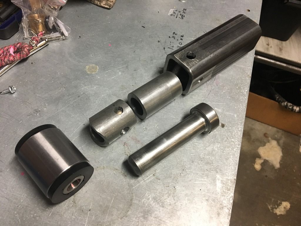
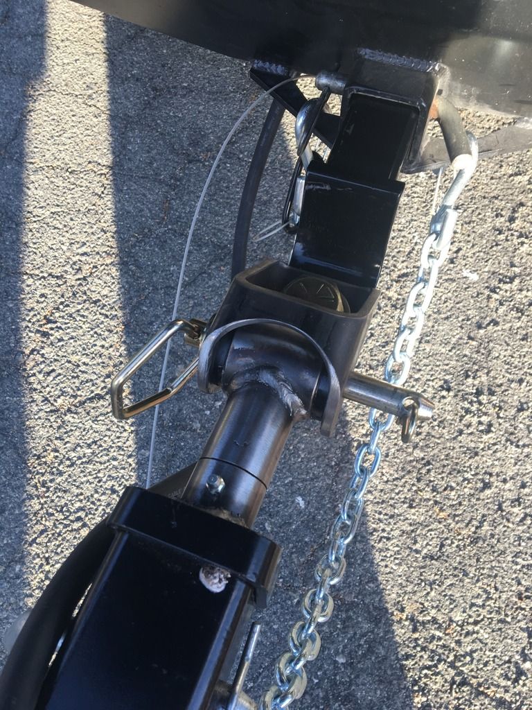
Im building a 3-axis coupler and I have a question for those of you that have used them. As you can see in the pic, I have a pin that rotates in a sleeve, allowing the coupler to roll. It started as an interference fit and I knew it would tighten up a bit. But, after full welding, it got a bit tighter than I expected. It won't even take grease. I know that it will loosen up, but it's driving me nuts. Anyone use a coupler that started out tight as hell then "broke in"?
Thanks, Matt

IMG_1571_zpsiil5tukc.jpg~original


IMG_1582_zpsrepjfeyn.jpg~original
 
Register to hide this ad
Is your Zerk bad by chance? Where did you get your parts to do this by the way?


Sent from my iPhone using Tapatalk
 
Is your Zerk bad by chance? Where did you get your parts to do this by the way?


Sent from my iPhone using Tapatalk

I think the zero is ok, just that tight. With the coupler in the trailer, I can turn it with a 2' bar... with effort. I've driven it around the block and obviously it moves. Maybe I'll just drive it a bit and see how it works out.

All the materials are basic. The pin is a grade 8 bolt and the rest is from the local steel shop. I was going to do a quick, detailed thread once it's finished.
 
I'd like to build one myself this summer, looking forward to your writeup


Sent from my iPhone using Tapatalk
 
I think the zero is ok, just that tight. With the coupler in the trailer, I can turn it with a 2' bar... with effort. I've driven it around the block and obviously it moves. Maybe I'll just drive it a bit and see how it works out.

All the materials are basic. The pin is a grade 8 bolt and the rest is from the local steel shop. I was going to do a quick, detailed thread once it's finished.

The welded sleeve is probably warped due to un even heat distribution that your going to get welding a round object into a square whole. I think the only thing you can do is let it break in since you can not take it apart and try and true up the bore due to its design. I have replaced a lot of pin bosses on Deere Skid steers and they use a Morse tapered pin and you have to get those set dead on or they will bind when you go to curl the bucket and if you concentrate to much heat to one side of the boss to long and it will pull it just a hair off.
Very cool hitch design by the way never seen any thing like this on automotive application only on construction equipment and AG impliments
 
Last edited:
3 way coupler

The finished piece looks great. Simple and functional. Looking at the parts I can't tell exactly how it fits together. I see the round tube piece that gets welded to the tube and black bushing. I don't see where the two holes went. I see the solid pin and assume you welded it into the trailer square tube. Where did the square tube go? And which parts are tight?
Wish I could fabricate steel like that. Nice work.
Dave
 
Thank you

The welded sleeve is probably wrapped due to in even heat distribution that your going to get welding a round object into a square whole. I think the only thing you can do is let it break in since you can not take it apart and try and true up the bore due to its design. I have replaced a lot of pin bosses on Deere Skid steers and they use a Morse tapered pin and you have to get those set dead on or they will bind when you go to curl the bucket and if you concentrate to much heat to one side of the boss to long and it will pull it just a hair off.
Very cool hitch design by the way never seen any thing like this on automotive application only on construction equipment and AG impliments

Thank you, that puts it into perspective and makes a lot of sense. I'm going to have that in mind when I make another. You're right, this is going to be hard to avoid, so I'm just going to loosen it up a bit. I have extra material, so I'm just going to make a new tonight and maybe turn this into a build thread. I have a few other things that I'm going to add for version 2.0.

Thanks again for the kudos!
Matt
 
The finished piece looks great. Simple and functional. Looking at the parts I can't tell exactly how it fits together. I see the round tube piece that gets welded to the tube and black bushing. I don't see where the two holes went. I see the solid pin and assume you welded it into the trailer square tube. Where did the square tube go? And which parts are tight?
Wish I could fabricate steel like that. Nice work.
Dave

Thanks, Dave! The piece of tube that is welded to the bushing, has holes that were drilled for rosette welds. I ground those off, so you can't see them in the finished pic. As for the square tube, it is flush with the trailer tongue tube and you can't really see it in the pic. I think I'm going to redo it tonight and post some better pics.

Matt
 
Thank you, that puts it into perspective and makes a lot of sense. I'm going to have that in mind when I make another. You're right, this is going to be hard to avoid, so I'm just going to loosen it up a bit. I have extra material, so I'm just going to make a new tonight and maybe turn this into a build thread. I have a few other things that I'm going to add for version 2.0.

Thanks again for the kudos!
Matt

What is your welding process are you using? Mig or stick kinda looks like a 6010 or 6011
 
Don't have any insight for the OP, just wanted to say nice job! Look forward to seeing your write up! I was planning to follow this one when I build mine.
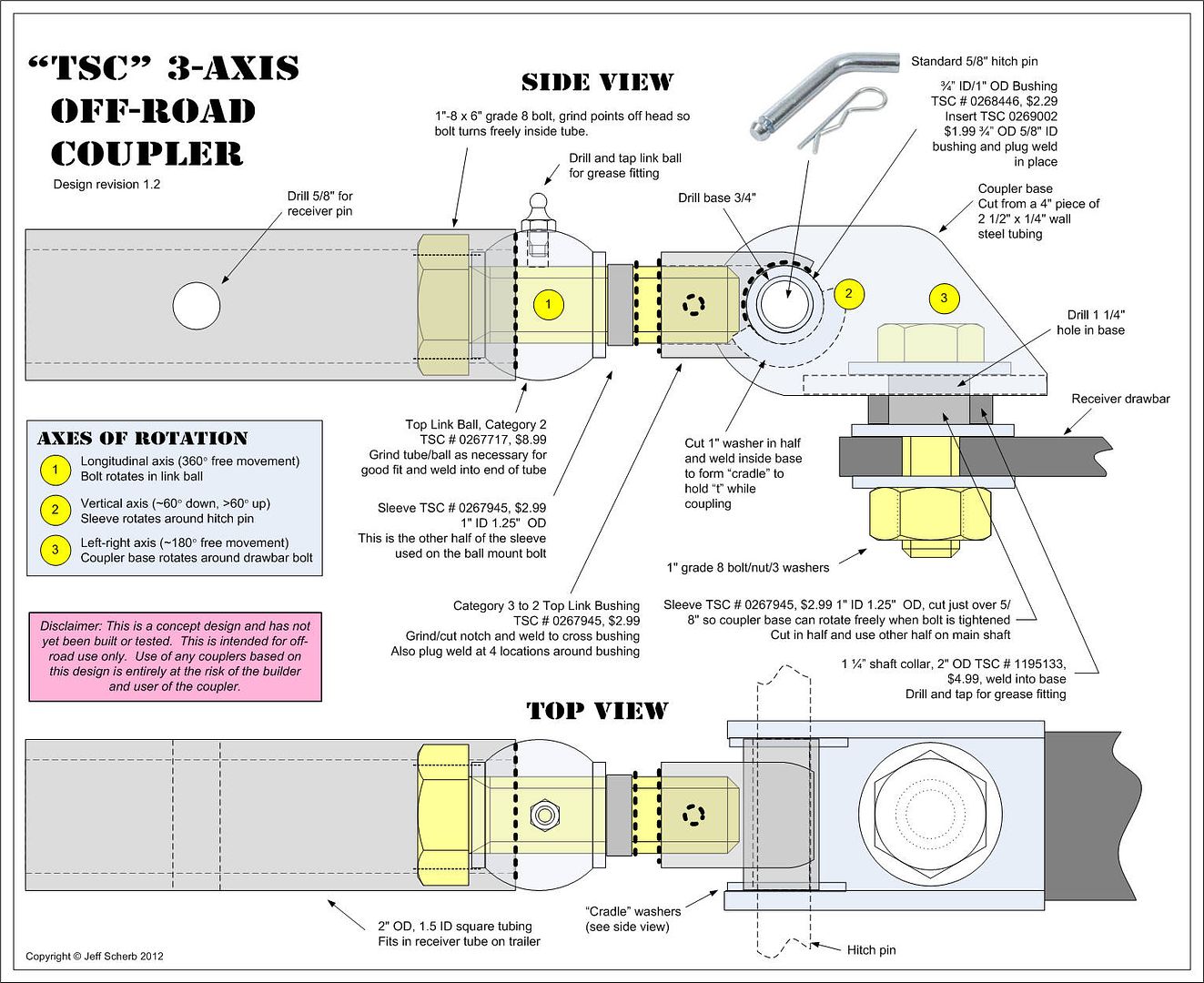
https://tventuring.com/trailerforum/thread-65.html
TSCCoupler12.jpg~original

Thank you! I'm really glad you referenced this, because this is one of the motivations behind my project. In fact, i used a few of those parts (bushings) listed on the vehicle end. The rest of it just seemed better suited coming from a steel shop. I'm going to try and get the new pieces cuy up tonight and I'll post them up.
 
Last edited:
It's MIG. I'm a big rusty and actually was never very good at pretty beads on tube joints.

This a 120v or 240v welder? If its a 120v I would suggest using a.035" self shield wire you will get better penatration on that .250 wall tube and be able to run the bead faster to help with that warping. Also if it was me I would weld the end of the bolt shaft on the very tip to the sleeve it welds to then clean that up and then weld it to the bushings sleeve to make it stronger along with the 4 plug welds you did. You can also wrap a damp cloth around the round tube while welding it to help absorb some of the heat to help prevent a warp
 
This a 120v or 240v welder? If its a 120v I would suggest using a.035" self shield wire you will get better penatration on that .250 wall tube and be able to run the bead faster to help with that warping. Also if it was me I would weld the end of the bolt shaft on the very tip to the sleeve it welds to then clean that up and then weld it to the bushings sleeve to make it stronger along with the 4 plug welds you did. You can also wrap a damp cloth around the round tube while welding it to help absorb some of the heat to help prevent a warp

It's 240V and handles .250 very well. If im understanding correctly, you mean the tip of the pin to the joint before the bushing?

hitch%201_zpsij279dxb.jpg~original


I actually did weld that part before i joinded it to the bushing.That joint at the bushing has a nice bevel and the HAZ on the backside was solid. I think I have good penitration (giggity)?

I appriciate your advice! Its nice talking this stuff out. I've got a new game for the sequence that I weld them up. I'm going to loosen up the tolerence on the pin, then weld that sleeve to the 2" receiver tube before I install the pin. that way i can deal with any fit issues. then ill cap it and finish weld it to the bushing, if that makes any sence.

Thanks again for the input!
Matt
 
It's 240V and handles .250 very well. If im understanding correctly, you mean the tip of the pin to the joint before the bushing?

hitch%201_zpsij279dxb.jpg~original


I actually did weld that part before i joinded it to the bushing.That joint at the bushing has a nice bevel and the HAZ on the backside was solid. I think I have good penitration (giggity)?

I appriciate your advice! Its nice talking this stuff out. I've got a new game for the sequence that I weld them up. I'm going to loosen up the tolerence on the pin, then weld that sleeve to the 2" receiver tube before I install the pin. that way i can deal with any fit issues. then ill cap it and finish weld it to the bushing, if that makes any sence.

Thanks again for the input!
Matt

Sounds like you got this knowing you got a 240v welder i have no doubts about ample penatration... he said penatration...
 
Did you turn that bolt head in a lathe, It looks like its perfectly rounded with no grinding marks.

No, I have a bad-ass Jet bench grinder, with a 4x36" belt. It's probably one of my favorite fab tools. All my stuff is done by hand.
 
Last edited:
Sharky's Coupler

So, instead of starting over with a new thread, I'm just going to add the build of version 2.0 to this thread. As I mentioned, the first one I made was just not working out the way I wanted. So, as I often do, I'm starting over. To start it off, here is a list of the players:
2"x2"x.250" square tubing
1.5"x.250" DOM round tubing
3"x3"x.250" square tubing
Poly bushing w/ 2"x.250 DOM sleeve http://www.barnes4wd.com/DOM-Sleeve-Poly-Bushing_p_137.html
1"x8" grade 8 bolt
1"x4" grade 8 bolt
(2) 1/4-28 zerks
(Tractor supplies for a sleeve and a collar(I'll give details later)

I put the measurements of the cuts on the first pic, but keep in mind that those numbers were reached with a combination of Chinese blueprinting, a WAG and a little bit of Santeria. My point is, they're not etched in stone.

This is the start of the rotating sleeve that I'm redoing
IMG_1586_zpsnymjrr9w.jpg~original


Hot, fish mouth action! I have a fairly decent notcher that is handy for roll cages.
IMG_1588_zpsaekuvbbg.jpg~original


Chop-chop! This is another tool that makes fabrication fun for the whole family. I love the dry cut saw for the clean, square cuts.
IMG_1589_zpsjg3icwz8.jpg~original


This is what it all looked like before I trimmed and fitted most of the holes you see are for plug welds, one is for a zerk. I'm pretty sure that there is a cheaper option for a pin, in lieu of the bolt, but this is what I could easily get. I think bar stock would be ok, but the bolt is a bit stronger.
IMG_1590_zps9vlnmito.jpg~original


At this point, I did a much better job of things, to fix my tightness issues. I turned the pin a bit, with my belt sander and got a nice, even slip fit. I'm going to change up my welding sequence, so I have a chance to hone the sleeve to fit the pin if need be. The bevel on the end of the pin, and on the notched tube, are going to help with penetration (giggity) for the welded joints. You may also notice that I cut a groove in the rotating sleeve for grease flow. Seemed like a good idea, hope it works.

IMG_1591_zpsczagnrue.jpg~original

IMG_1592_zpsdt7nmzbo.jpg~original


This is as far as I got tonight. I had hoped to get it welded up, but my dog came in the garage and, well, he died. That was some crazy $h:t! I'm not mentioning this to elisit a response. He was old, he had issues and that's life. But, he was a cool little dude and had one hell of a back-story. So, this coupler is in honor of Sharky Shooter. Godspeed lil' buddy!
IMG_1180_zpsiur4ymzq.jpg~original


Thank you guys for the help and nice comments. I'll get the rest posted up ASAP.
Matt

 
Last edited:
Mats Coupler

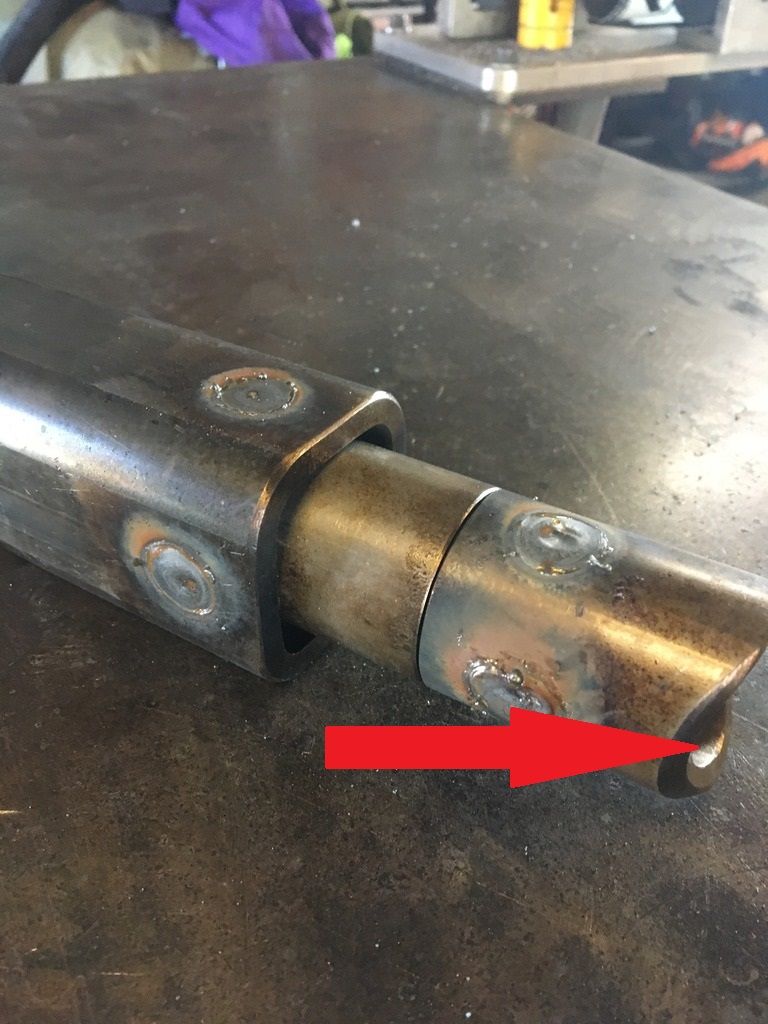
Back at it! As stated, I changed up my sequence and burned the sleeve in first. I definitely slowed down and kept the sleeve as cool as possible. The pin as it should and all is well. Should have done it this way in the first place, but hindsight is always 20/20.

IMG_1594_zpsa8hm5km9.jpg~original

IMG_1595_zpso5gto2x6.jpg~original


While that was cooling, I took a few pics of the truck side of the hitch. I made this out of a piece of 3x3x.250 that I found in scrap bin. With the price of steel, I'm not too proud to dumpster dive. This is basically a copy of the schematic that snOwrunner posted. Same tractor part, but larger tube to fit the poly bushing. The collar that is welded to the tube is tapped for a zerk.

IMG_1596_zpsgctfigxi.jpg~original

IMG_1598_zpsz2gx5njs.jpg~original

IMG_1599_zpshmm1wrqh.jpg~original


So, at the end of the night, I had what I was looking for. Everything moves perfectly and now I just need the new bushing to show up. I'll follow up in a day or so. Thanks again for the advice!
Matt
 

Members online

Forum statistics

Threads
278,304
Messages
3,554,041
Members
248,016
Latest member
Advally Service

Trending content

Back
Top