Hiway Warrior
New member
Radio Repair – Intermittent Dial Lights
(2000 4R)
This addresses intermittent dial lighting on the standard AM/FM/CD/Cassette radios in many 2000 4-Runners. The lights usually start blinking out occasionally, but then come right back on; both in daytime and when dash lamps are on. Eventually, the radio lights go off more often and finally hitting the dash or pressing on the front of the radio will bring them back on only for a second or so. The rest of the radio system continues to work as before.
After messing around with this problem for quite some time, I decided to make a serious effort to find out what was going on here, as many owners have complained about this on the blogs and eventually gave up and replaced the unit with a new system. In a nutshell, here’s what I found.
Suspected Cause
The cause of this blinking out of the lights is an intermittent connection. This can be almost anywhere, but the most frequent locations I’ve found are:
• The rear plug of the radio where the harness plugs into the radio. While it’s possible the harness/connectors may affect this if they are corroded, I’ve found this never to be the case. Inside the radio, the plug receptacle is screwed to the PC board and has 2- rows of lugs that are soldered to the board. (Photo 7) The PC board used in these radios is a sophisticated (for year 2000 cars) double-sided board that is flow-soldered on both sides after the components are placed on it, and the chance for an incomplete, cold, or loose solder joint is always there. I should note that these boards are of high build quality and QC on these types of boards is generally pretty good.
• Other components can also have broken or intermittent cold solder joints. This can be very time consuming to troubleshoot, as no circuit diagrams / schematics are available that I am aware of.
• The control face of the radio can also have internal problems that affect the lighting. I have not experienced this. All front faces I have seen were proven to be good by swapping to a known good radio.
Disassembly of Radio
For access to test, the radio must be removed from the car and partially disassembled. It can then be partially reinstalled for testing.
1. Remove dash cover around radio: Covered in other areas of this site.
2. Remove 4 bolts holding radio in dash.
3. Pull radio partially out and disconnect antenna, power antenna plug-next to antenna plug, and white multi-pin radio plug. Like most Toyota plugs, there is a push-unlock mechanism on the plug. (Photo 2)
4. Radio will now come out.
5. For re-soldering on the PCB, you will need to remove the CD player and the cassette players.
a. Remove top & bottom of radio. Gently pry off with a flat blade screwdriver.
b. Remove face plate of radio – use tooth picks to hold tabs up so face can be gently pulled off. Remove CD dust protector if it doesn’t already fall off. (Photo 4)
c. Remove (2) small hex bolts (Photo 5) behind face place on radio chassis & (2) Torx bolts in back of CD player. Pull CD player up to withdraw. No wires to worry about; it connects via pins and a plug on the PCB.
d. Flip radio over and unscrew (4) Torx bolts holding in cassette player. Partially remove cassette player and note ribbon connector. Carefull! – there is a ribbon connector that needs to be gently pulled out of its place on the PCB. Use needle nose pliers or hemostats. Note that the black dot on the ribbon is facing the chassis wall and reinstall correctly later. (Photo 6)
e. You may now reinstall the face plate and the radio part will be functional.
Troubleshooting, Results, and Repair
1. Since I have (3) 2000 4-Runners, I used the opportunity to compare the good one with the vehicles that have the intermittent radio lights. I compared the voltages on the plug that comes into the radio from the harness with the radio on and the exterior lights (headlamps – parking lamps) both on and off. During daylight driving the radio dial is fully illuminated without the ability to dim the face. At night time when the headlamps / parking lamps are on the radio face is dimmable with the dash mounted dimmer control. I created a chart to show the voltages in each of the 2 headlamp switch positions (off & on). Results: Voltage is getting to the radio equally on all (3) 4-Runners. Hence, no wiring loom, fuse, or other issues stopping voltage from getting to the radio connector itself.
2. Next I wanted to see if the voltage was making it to the PCB inside the radio. I removed the top cover of the radio and hooked it up in the car. I measured the voltage on the inside of the radio next to where the plug lugs are soldered to the PCB. I again went through the process as above and the voltages were the same…..voltage is making it to the PCB. When I was measuring the voltage at the PCB on the lugs I noticed the dial lamps went on & off intermittently. Results: Cold solder joint from the plug lug(s) to the PCB. It is difficult to solder the outside row of lugs due to the small size and spacing of the lugs. However, it is almost impossible to solder the inside row of lugs without removing the outside row first. Repair: I carefully snipped the outside row or lugs where they make a 90 degree turn from the plug, down to the PCB, and de-soldered them from the PCB. I then re-soldered the inside row of lugs, carefully checking under magnification if both side of the PCB were properly soldered. After that I attached small wires from the cut lugs and wired them back to their proper locations. Re-assembled the radio & tested. Still working to this day. Keeping my fingers crossed. (Photos 8, 9, 10)
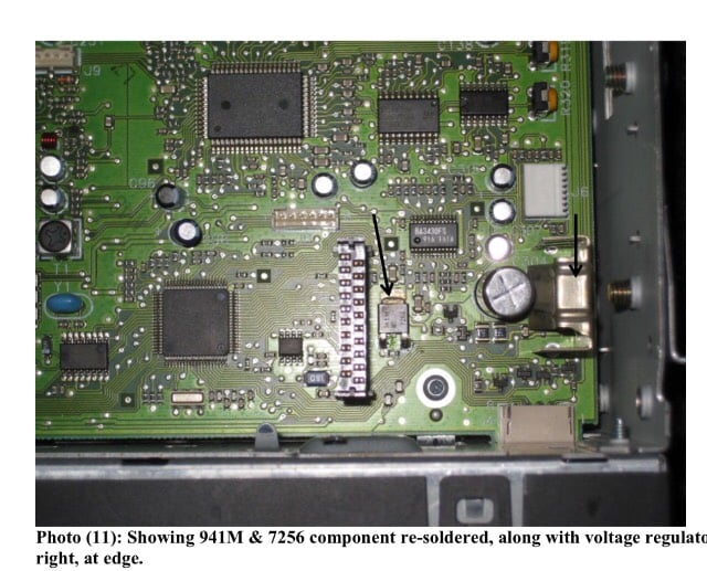
3. On a different radio I found a component solder joint had failed. I located this joint with the help of circuit freeze spray and light tapping / pushing with a plastic probe. This is noted in the photos. Repair: I re-soldered the joint, along with several others nearby that looked possibly suspicious, and the results were successful. The components were a 3-pin semiconductor identified as 941M & 7256 and a 7-pin v. regulator. (Photo 11)
(1) Combo AM/FM/Cassette/CD Unit
Photo (2): Rear of above unit showing input / output plug discussed in text (L). Plastic plug on right is not used. Power antenna & antenna signal plugs are next on right edge.
Photo (3): ID tag on side of unit
Photo (4): Showing with top cover off and CD player removed. Using toothpicks to remove front face.
Photo (5): Face off showing CD dust cover & two front screws. Be sure to replace before installing front face.
Photo (6): Cassette player preparing to remove. Note ribbon cable at top; unplug from PC board with care.
Photo (7): Main plug as found. Note 2 rows of tabs.
Photo (8): Outer row of legs of plug cut / removed to allow soldering of inner legs.
Photo (9): Outer legs replaced with wire. Only wired legs need replacing. See diagram showing unused legs.
Photo (10): Underside of plug legs also re-soldered. Double sided PCB!
Photo (11): Showing 941M & 7256 component re-soldered, along with voltage regulator to right, at edge.
Photo (12): View of entire PCB from top showing repaired plug.
Photo (13): Top view showing installed CD player & repaired plug in rear.
NOTES:
1. The components on this PCB are tiny! Be very careful when working on the PCB. A slight solder splash or loose piece of solder can ruin the job and cause a host of other problems you didn’t have before.
2. Use a suitable grounded soldering iron tip and temperature controlled soldering iron.
3. Do not take on this project if you need your car soon! Have patience and give up for a while when you get tired or frustrated.
4. Use a magnifying glass or lighted magnifier. You have to be able to check your work under magnification. I used a 10x lens to check work and a lighten 3x lens to perform the work.
5. Cleanliness! Work cleanly and blow off dust or particles from the PC board.
(2000 4R)
This addresses intermittent dial lighting on the standard AM/FM/CD/Cassette radios in many 2000 4-Runners. The lights usually start blinking out occasionally, but then come right back on; both in daytime and when dash lamps are on. Eventually, the radio lights go off more often and finally hitting the dash or pressing on the front of the radio will bring them back on only for a second or so. The rest of the radio system continues to work as before.
After messing around with this problem for quite some time, I decided to make a serious effort to find out what was going on here, as many owners have complained about this on the blogs and eventually gave up and replaced the unit with a new system. In a nutshell, here’s what I found.
Suspected Cause
The cause of this blinking out of the lights is an intermittent connection. This can be almost anywhere, but the most frequent locations I’ve found are:
• The rear plug of the radio where the harness plugs into the radio. While it’s possible the harness/connectors may affect this if they are corroded, I’ve found this never to be the case. Inside the radio, the plug receptacle is screwed to the PC board and has 2- rows of lugs that are soldered to the board. (Photo 7) The PC board used in these radios is a sophisticated (for year 2000 cars) double-sided board that is flow-soldered on both sides after the components are placed on it, and the chance for an incomplete, cold, or loose solder joint is always there. I should note that these boards are of high build quality and QC on these types of boards is generally pretty good.
• Other components can also have broken or intermittent cold solder joints. This can be very time consuming to troubleshoot, as no circuit diagrams / schematics are available that I am aware of.
• The control face of the radio can also have internal problems that affect the lighting. I have not experienced this. All front faces I have seen were proven to be good by swapping to a known good radio.
Disassembly of Radio
For access to test, the radio must be removed from the car and partially disassembled. It can then be partially reinstalled for testing.
1. Remove dash cover around radio: Covered in other areas of this site.
2. Remove 4 bolts holding radio in dash.
3. Pull radio partially out and disconnect antenna, power antenna plug-next to antenna plug, and white multi-pin radio plug. Like most Toyota plugs, there is a push-unlock mechanism on the plug. (Photo 2)
4. Radio will now come out.
5. For re-soldering on the PCB, you will need to remove the CD player and the cassette players.
a. Remove top & bottom of radio. Gently pry off with a flat blade screwdriver.
b. Remove face plate of radio – use tooth picks to hold tabs up so face can be gently pulled off. Remove CD dust protector if it doesn’t already fall off. (Photo 4)
c. Remove (2) small hex bolts (Photo 5) behind face place on radio chassis & (2) Torx bolts in back of CD player. Pull CD player up to withdraw. No wires to worry about; it connects via pins and a plug on the PCB.
d. Flip radio over and unscrew (4) Torx bolts holding in cassette player. Partially remove cassette player and note ribbon connector. Carefull! – there is a ribbon connector that needs to be gently pulled out of its place on the PCB. Use needle nose pliers or hemostats. Note that the black dot on the ribbon is facing the chassis wall and reinstall correctly later. (Photo 6)
e. You may now reinstall the face plate and the radio part will be functional.
Troubleshooting, Results, and Repair
1. Since I have (3) 2000 4-Runners, I used the opportunity to compare the good one with the vehicles that have the intermittent radio lights. I compared the voltages on the plug that comes into the radio from the harness with the radio on and the exterior lights (headlamps – parking lamps) both on and off. During daylight driving the radio dial is fully illuminated without the ability to dim the face. At night time when the headlamps / parking lamps are on the radio face is dimmable with the dash mounted dimmer control. I created a chart to show the voltages in each of the 2 headlamp switch positions (off & on). Results: Voltage is getting to the radio equally on all (3) 4-Runners. Hence, no wiring loom, fuse, or other issues stopping voltage from getting to the radio connector itself.
2. Next I wanted to see if the voltage was making it to the PCB inside the radio. I removed the top cover of the radio and hooked it up in the car. I measured the voltage on the inside of the radio next to where the plug lugs are soldered to the PCB. I again went through the process as above and the voltages were the same…..voltage is making it to the PCB. When I was measuring the voltage at the PCB on the lugs I noticed the dial lamps went on & off intermittently. Results: Cold solder joint from the plug lug(s) to the PCB. It is difficult to solder the outside row of lugs due to the small size and spacing of the lugs. However, it is almost impossible to solder the inside row of lugs without removing the outside row first. Repair: I carefully snipped the outside row or lugs where they make a 90 degree turn from the plug, down to the PCB, and de-soldered them from the PCB. I then re-soldered the inside row of lugs, carefully checking under magnification if both side of the PCB were properly soldered. After that I attached small wires from the cut lugs and wired them back to their proper locations. Re-assembled the radio & tested. Still working to this day. Keeping my fingers crossed. (Photos 8, 9, 10)
3. On a different radio I found a component solder joint had failed. I located this joint with the help of circuit freeze spray and light tapping / pushing with a plastic probe. This is noted in the photos. Repair: I re-soldered the joint, along with several others nearby that looked possibly suspicious, and the results were successful. The components were a 3-pin semiconductor identified as 941M & 7256 and a 7-pin v. regulator. (Photo 11)
(1) Combo AM/FM/Cassette/CD Unit
Photo (2): Rear of above unit showing input / output plug discussed in text (L). Plastic plug on right is not used. Power antenna & antenna signal plugs are next on right edge.
Photo (3): ID tag on side of unit
Photo (4): Showing with top cover off and CD player removed. Using toothpicks to remove front face.
Photo (5): Face off showing CD dust cover & two front screws. Be sure to replace before installing front face.
Photo (6): Cassette player preparing to remove. Note ribbon cable at top; unplug from PC board with care.
Photo (7): Main plug as found. Note 2 rows of tabs.
Photo (8): Outer row of legs of plug cut / removed to allow soldering of inner legs.
Photo (9): Outer legs replaced with wire. Only wired legs need replacing. See diagram showing unused legs.
Photo (10): Underside of plug legs also re-soldered. Double sided PCB!
Photo (11): Showing 941M & 7256 component re-soldered, along with voltage regulator to right, at edge.
Photo (12): View of entire PCB from top showing repaired plug.
Photo (13): Top view showing installed CD player & repaired plug in rear.
NOTES:
1. The components on this PCB are tiny! Be very careful when working on the PCB. A slight solder splash or loose piece of solder can ruin the job and cause a host of other problems you didn’t have before.
2. Use a suitable grounded soldering iron tip and temperature controlled soldering iron.
3. Do not take on this project if you need your car soon! Have patience and give up for a while when you get tired or frustrated.
4. Use a magnifying glass or lighted magnifier. You have to be able to check your work under magnification. I used a 10x lens to check work and a lighten 3x lens to perform the work.
5. Cleanliness! Work cleanly and blow off dust or particles from the PC board.