97 Limited 5 speed swap

Now would be a good time to do new shifter seats...

The manual transmission transfer case will be missing the 'neutral' switch - that is only used on the autos for the "ATP" light that warns you when the trans is in park and the transfer case is in neutral.

-Charlie
 
Now would be a good time to do new shifter seats...

The manual transmission transfer case will be missing the 'neutral' switch - that is only used on the autos for the "ATP" light that warns you when the trans is in park and the transfer case is in neutral.

-Charlie
I thought I had pulled a third off of the adapter between transmission and transfercase and was sure there were three because of the wiring diagram but nope.

Transfercase wasn't leaking/seeping at all and I didn't pull the shifter. Transmission shifter seal I plan to do. I will definitely need to do the transmission output shaft seal as that took a beating on its way out.


Yesterday I didn't get much done as we had both kids, plus 3 more of their cousins.... I did find time to try and install the clutch on the limited.

Found a very nice speaker crossover... installed right in the way, so had to remove that.

Then i realized now was the time to uninstall the aftermarket alarm.... sigh.

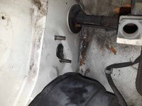
Then when it came time to drill holes..... someone had drilled through the firewall right where the CMC would mount, about a 1" hole for a ~14ga wire, and in the wrong spot.

The existing hole was completely in the way. My method was that I marked where I wanted them and drilled around the perimeter with a very small drill bit then enlarging slowly, (I did start by drilling the center and using a step bit...however tye existing hole caught the bit and pulled it off center). Cleaned it up with a step bit... it's ugly but seems to fit. I'll find a way to seal it, even if I have to be a bit ghetto. Pictured will come soon.
 
Last edited:
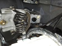
CMC is installed and brake pedal swapped.

What do people do for the hydraulic line.... zip tie it or weld on the tab to the cab from the donor?
 

Attachments

  • 20201025_094108_compress7.jpg
    20201025_094108_compress7.jpg
    127.9 KB · Views: 380
  • 20201025_094125_compress15.jpg
    20201025_094125_compress15.jpg
    127.4 KB · Views: 379
CMC is installed and brake pedal swapped.

What do people do for the hydraulic line.... zip tie it or weld on the tab to the cab from the donor?

For mine, I just used the bracket off the bellhousing bolt for the trans side of the soft line and left the other end free floating, mine was wedged tight enough next to the body that I wasn't really worried about it. If I have issues later, I'll probably bolt on a tab. I would rather bolt on the tab than weld it, with all the insulation in that area.

Also using a beer carton oil soaked gasket for the clutch cylinder, since my donor's disintegrated.
 
Old drivetrain gone....

Now I'm a bit shocked by what I see.

It isn't uncommon to have varying parts or wiring between trim levels...

Buy the body is literally stamped different between an SR5 and a limited.

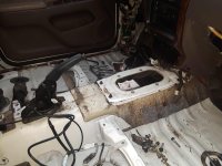
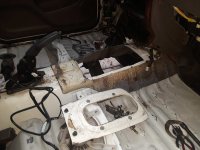
The limited has a very different opening at the center console than the SR5.... the floor plans are literally stamped different instead of having a variation of something that simply bolts (or even rivets) in place.

Guess I'll be cutting it here soon...
For the shifter cutout in the transmission tunnel, try to keep the bolts as untouched as possible. I can take a picture of what I did, but I managed to bolt the manual trans boots (TBF mine were from a tacoma) onto the 2 bolts that were 1 row down from the very top. Then I cut up the auto shifter metal and welded it to the bottom of the shifter boots so I could use the bottommost 2 bolts to get a good seal. Wasn't very hard, but make sure to hold your breath while welding, the shifter boot metal bracket is galvanized.
 
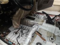
I decided to cut the tunnel top off of both vehicles, will trim as needed and weld in, then seam seal. It seemed the best option to make it all work as designed.
 

Attachments

  • 20201025_171258_compress72.jpg
    20201025_171258_compress72.jpg
    132 KB · Views: 354
  • 20201025_171306_compress93.jpg
    20201025_171306_compress93.jpg
    129.7 KB · Views: 343
Last edited:
Mostly done, waiting for seam sealer for the underside and might put a rubberized coating coating.


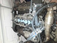
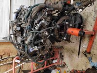
Might also have the oiliest engine that didn't drip on the ground.... will get a plethora of new gaskets.
 

Attachments

  • 20201026_224749_compress59.jpg
    20201026_224749_compress59.jpg
    128.9 KB · Views: 367
  • 20201027_154223_compress48.jpg
    20201027_154223_compress48.jpg
    121.9 KB · Views: 329
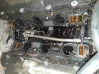
In mild tear down of the engine to do the valve cover gaskets and injector O-rings, I came across sealant falling off of what I learned was the back of the bypass plate/tube.

Does this need to be removed and resealed? It seems that this really just covers the empty space between heads/block/lower intake and seems to be a bit of a dust cover.

I have all the gaskets if needed.... just wondering I need to pull and seal it... or if I can clean it up well and RTV it externally.
 
The valve cover gasket replacement is quickly becoming a much bigger project....

Anyone have head torque specs and sequence?


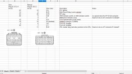
Here is how I handle wiring differences. I look at the diagrams to determine what needs to go where. Toyota ECUs tend to be pretty self contained for wiring but still need to be wired to the body.

The main ecu plugs I won't handle since I pulled the entire harness... though I have a few things in my head that may vary... will see how that goes.

Much to my chagrin the body plug is different.

So I looked for what I thought to be body side connections (example- to the combination meter/gauges). Then verify those plugs seem to be right, then create a basic layout in Excel to show what pin, wire color, and which plug on dealing with. Since these are both 97s the wire colors are the same but, if they were different years, I would do the same except show the wire color differences.

When I swapped a 91 5sfe into an 86 MR2 I did the same thing without even cutting the factory body harness (this time that won't happen) but wiring in took maybe 2 hours... and that was for completely different bodies and engines.
 

Attachments

  • 97 ECU Body Plug_compress10.jpg
    97 ECU Body Plug_compress10.jpg
    122.7 KB · Views: 316
Last edited:
When I swapped a 91 5sfe into an 86 MR2 I did the same thing without even cutting the factory body harness (this time that won't happen) but wiring in took maybe 2 hours... and that was for completely different bodies and engines.
I have not had the same experience with my Camry 3s-gte/3s-ge swaps... :becky:

AA6uOpVh.jpg


-Charlie
 
I have not had the same experience with my Camry 3s-gte/3s-ge swaps... :becky:

AA6uOpVh.jpg


-Charlie

Ha, fair enough. The 3s shouldn't be all that different in how the wiring works. The ecu should be relatively self contained other than ignition, circuit opening relays, and dash/gauges. The alltrac, if it has a CDL, would need the switch wired as well,but generally most of the engine wiring is self contained. There could be a couple/few connections elsewhere in the engine bay (like power or an AC idle up).

My point was really... if I spend a little time organizing the wiring in a simple spreadsheet, then the ~20 wires needed to swap become very easy as I have the spinouts, wire color, and function of every wire. Toyota is also generally pretty good about the wiring naming conventions they use.
 
Those projects were complicated by the RHD vs. LHD wiring harnesses, so basically EVERY wire had to be moved/adjusted. Also, a few more things than you'd think ran through the engine harness from the engine bay fuse box into the car, rather than through the fender harness.

I do agree that Toyota is good about wire colors, fuse names, etc. that make it easier.

The 4Runner engine/trans harness is much better contained. I used a '97 donor on the 4WD swap in my '99 and had to play some tricks to add the pins to the 2WD engine harness as locations and pin sizes changed on basically all the relevant connections. Luckily, its only a few wires...

-Charlie
 
The hope was to get the engine/trans and tansfercase into the Limited this weekend but I just don't see it happening.

We have light shows tonight and all of tomorrow night and setting up our big Christmas tree for the holiday light show on Sunday. I'm a bit behind on some of the other props as well.

The motor is still on the stand in pieces and I have a fun bolt to attempt to extract from the flywheel due to stupidity and chance.
 
And the knock sensor harness just disintegrated during the bypass hose reinstall. If Toyota doesn't have it and can't get it I'm stuck for a few days.
 
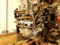
Motor is ready....ish.

Toyota had the harness. Unfortunately the gasket kit was missing the upper manifold set, but they looked fine for reuse.

Unfortunately I wasn't able to extract the bolt (drilled just off center and the extractor dug into the flywheel) so new flywheel needs to go on once off the stand.

Maybe this week I'll do that and get the trans on.

Still needing to set up for Christmas and only have about 20 days....
 

Attachments

  • 20201102_205719_compress87.jpg
    20201102_205719_compress87.jpg
    127.2 KB · Views: 536
  • 20201101_210824_compress8.jpg
    20201101_210824_compress8.jpg
    129.6 KB · Views: 525
Last edited:
If anyone is still reading... aside from a couple pixels to replace (out of more than 8,000) the show is physically and running - which means back to the 4Runner.


Motor got the new clutch kit & flywheel, bolted the transmission back on.

Started the wiring and I am, at least what I thought, about 90% done.


However I want to verify the wiring between

II1, II2, and II3. These are the connectors on the glove box. II2 is non existent in the SR5. II3 pretty full with wires in the Limited (2 of which run to the manual ecu I am rewiring) and the SR5 only has 4 wires.


However... I can't seem to find a pinout for any of these connectors.

In the EWD it just shows a rectangle as a connector. The information just references page 40, which is the connectors and ground splices - showing an illustration of the connector, but no pinout. The ECT diagram does the same thing.

Anyone happen to have a pin out or know wherei could find one? Thanks.
 
Never mind.... it will take some time but the rectangles are marked with the pin number.
Yup. Not having a specific location with each harness connector and its wiring is my only gripe about the Toyota diagrams.

If you have digital copies, you can do a search of the PDF and find all the locations and make your own notes/spreadsheet with the info you need.

-Charlie
 

Members online

Forum statistics

Threads
278,316
Messages
3,554,106
Members
248,016
Latest member
Advally Service

Trending content

Back
Top