A/C light flashing??

haha,, sweet!!!! I am very interested to see what the hells in there!! Keep us posted (uhh excuse the pun)
 
Update; Patrznet just notified me that this relay is on national backorder, and will not be available for at least one month.:mad:

I tried the local Toyota dealer, they want $70.64, and it will take 2/3 days to get it.:mad: :mad: :mad:

Fortunately, the relay I swiped from the fog lights is working, so I guess I will be waiting a while for the new one.
 
I got the same 'national back-order' message from Partznet this morning after wondering why I hadn't received my parts yet. I just took a look at the wiring manual and believe it points to the cause of the premature relay failure. This relay is switching an inductive load but doesn't have a mechanism to absorb the "kick back" EMF produced when the load is de-energized. The energy very likely escapes the system by arc'ing across the open relay switch contacts.

Over time, this design is likely to cause the relay contacts to fail to properly conduct current. Possible failure modes are stuck open or intermittent stuck open, or even stuck closed. Any of these faults will result in a failure of the compressor lock sensor circuit. The A/C control module will respond by blinking the light and shutting down the compressor. If your failure was the stuck closed type, banging the relay on the counter could bring it back to life (temporarily).

I'm going to try swapping the relay with my fog lights (until my new relay comes) AND adding a reverse polarity diode across the switch contacts to dump the inductive load back to the supply. My guess is the new relay has the diode built in or it uses a more durable switch contact material/size so it can withstand this kind of punishment longer.

UPDATE: See later posts -- you need to install the diode between pin #3 and GND, not as pictured in the next post.
 
Last edited:
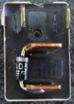
Here's the intended orientation of the protection diode. I don't advise anyone else try this since my relay didn't survive the heat from the soldering iron -- ended up dead completely. :bash:

UPDATE: This circuit doesn't work -- see later posts for the correct solution.
 

Attachments

  • protection diode.jpg
    protection diode.jpg
    22.6 KB · Views: 9,330
Last edited:
Since my relay is now completely dead, I thought I'd go ahead and confirm a few theories.

A) This is a mechanical relay -- OK, I already knew that since I could hear it clicking on/off on the bench.

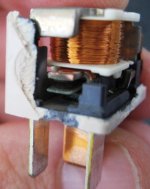
B) The charring around the relay contacts supports the theory that arcing is causing the premature failure. A diode as pictured above would solve this problem.
 

Attachments

  • relay contact charring.jpg
    relay contact charring.jpg
    69.6 KB · Views: 9,249
Last edited:
rando said:

B) The charring around the relay contacts supports the theory that arc'ing is causing the premature failure. A diode as pictured above would solve this problem.

Thanks for the disection Rando. Good info.
I don't have a relay failure yet but am out of warranty so I would like to do some prevention.
Since the durable relay is hard to get would it help to splice the diode somewhere else in the circuit (due to the solder heat at the relay)? What are the specs on the diode you suggest?
Thanks again.
 
Any general purpose rectifier should be fine (ex: 1N400x series). I used a 1N4005 equivalent part. It's rated at 1A (far more than the inductor kickback will produce) and 600V reverse voltage tolerance which means it should survive the nasty load load dumps and other transients that appear from time to time on the automotive alternator/battery supply rail.

I went ahead and moved the Fogs relay over since it's unlikely I'll need them anytime soon. For now, I just went ahead and installed the diode as pictured -- just without the solder (i.e. surface tension only). When I get some more time, I'll look for an easy and safe spot to install it. The wiring manual suggests there are a couple of junctions in that circuit. The A2 socket at the compressor clutch / sensor might be a viable option -- in this case you'd hook the diode anode to ground (UDPATE: In fact this is the proper solution) .

An obvious alternative would be to build a small harness including the diode to fit between the relay and the socket, using blade connectors.
 
Last edited:
rando said:
Since my relay is now completely dead, I thought I'd go ahead and confirm a few theories.

A) This is a mechanical relay -- OK, I already knew that since I could hear it clicking on/off on the bench.

B) The charring around the relay contacts supports the theory that arc'ing is causing the premature failure. A diode as pictured above would solve this problem.

Nice detective work. I'm not used to seeing mechanical relays sealed like that, Thats why I thought it might be a SSR. I guess it is to keep them clean given the environment they work in. Though some of the other relays in the box aren't sealed, in any case. Those contacts are, with out a doubt, burnt. I'm hoping the fog light relay holds out until the new relay is available again. I think the original A/C relay lasted 3 years, so I hope we have some time before the next one fries.
 
It turns out that soldering the diode DID NOT do further damage to my relay -- I simply made a mental mistake when testing the relay on the bench, post soldering.

More importantly, with the case removed, I can confirm that the diode isn't shunting the kickback (i.e. I can see an arc every time the relay contacts open). Apparently I made a 2nd mental mistake since the diode as installed can't possibly redirect the EMF since it will always be reverse biased. The bypass needs to go to ground. There isn't a ground rail available to this relay, so the bypass diode will have to be installed elsewhere in the circuit.

I'll post an updated solution when I have it -- sorry for any confusion.
 
Last edited:
TechWrench said:
Those contacts are, with out a doubt, burnt. I'm hoping the fog light relay holds out until the new relay is available again. I think the original A/C relay lasted 3 years, so I hope we have some time before the next one fries.

I tried to capture a video of the arcing but, as expected, it's too fast to be caught by my digicam.
 
Thanks for the update Rando. I was wondering about the way you wired the diode but wasn't quite sure myself. Now we know.

So I went to poke around under the hood and look in the fuse box. Turns out I don't have to worry about this because the following applies...

webshot said:

The relay that came with the car and is faulty is part number 90987-02022 and is white in color.

It is supposed to be replaced by the newer relay part number 90987-02028 and is grey in color.

This relay is found in the fuse box under the hood marked as "MG CLT". "MG CLT" is short for Magnetic Clutch.

My '04 SR5 already has the grey relay.
Good luck guys.
 
SOLUTION: MGCLT Relay Mod

The narrative in the following posts describes how I mod'd the magnetic clutch / magnetic clutch sensor circuit to prevent premature failure of the MGCLT relay. In my case, the relay had already failed before I learned of the problem. To test this modification I further destroyed my relay by removing it from its casing. Had the modification been in place earlier, I believe relay failure (and a costly $50+ replacement) could have been avoided.

This modifcation done correctly or not may start your truck on fire, or otherwise cause damage or injury to people, property, or the universe. It worked for me, as described, but I cannot guarantee that it is safe or that it will work for you. By attempting this modification, you agree to proceed at your own risk and accept full liability for your actions and their consequences. The information provided here is for informational purposes only. I do not endorse this modication nor recommend that ANYONE actually perform what is described.

 
Last edited:
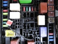
These are the locations to connect the diode. The diode is hidden underneath the heat shrink. The red sticker indicates the diode anode.

Anode goes to GND - Pin #4 (center pin) of the Heater relay
Cathode (striped side of diode) goes to the load - Pin #3 of MG CLT relay
 

Attachments

  • diode bypass.jpg
    diode bypass.jpg
    33.4 KB · Views: 7,242
Last edited:
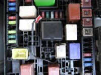
Here's what it looks like with the relays installed. Hopefully your MG CLT relay doesn't look like mine! :biggrin2:

If you're just reading these last two posts, I've confirmed that this eliminates the arcing inside of the relay. If you have the old style relay and it hasn't failed yet (and you're out of warranty), you can save yourself $50+ and install the bypass for < $1.
 

Attachments

  • diode bypass 2.jpg
    diode bypass 2.jpg
    31.1 KB · Views: 10,196
Last edited:
The diode goes across the coil of the relay which one side is ground, so if that pictured diode is across the coil and positioned correctly; then it should work fine to prevent a reverse huge voltage spike when the relay de-energizes.
 
greasefingers said:
The diode goes across the coil of the relay which one side is ground, so if that pictured diode is across the coil and positioned correctly; then it should work fine to prevent a reverse huge voltage spike when the relay de-energizes.

No. In this application, the diode is across the load (i.e. the magnetic clutch solenoid), not the relay coil. Without it, the EMF arcs across the relay switch contacts and dissipates into the battery supply circuit. With the diode, the EMF is redirected to ground.
 
rando said:


More importantly, with the case removed, I can confirm that the diode isn't shunting the kickback (i.e. I can see an arc every time the relay contacts open).

Got ya. If I had read the above more closely then I would have understood.

Nice job Rando!
 
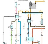
Here's the modified circuit. Per the diagram, you could tap D1 at connector IC4 with an in-line tap to get a cleaner install. IC4 is behind the driver kick panel.
 

Attachments

  • circuit.jpg
    circuit.jpg
    63.8 KB · Views: 12,096
Last edited:

Members online

Forum statistics

Threads
278,306
Messages
3,554,045
Members
248,016
Latest member
Advally Service

Trending content

Back
Top