blueblur1984
New member
I like the idea of having lots of aftermarket accessories but have learned over the years not to mess with something that is not broken...specifically the unmolested factory wiring in my t4r. I found this write up and though it was a nice compromise:
4Runners.org- Installing a Fused Distribution Box
Here is my spin on this build.
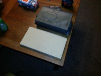
The first step was deciding where I wanted my fuse box and negative distribution panel to be...after some thought the path of least resistance seemed preferable. I uninstalled the 12 CD changer (that doesn't work with my updated cd player any how) and used it as a template to cut out some particle board.
<a href="http://www.flickr.com/photos/96555314@N02/8860710259/" title="cell phone pics 613 by blueblur19841, on Flickr"><img src="http://farm4.staticflickr.com/3827/8860710259_90b2e5ee28.jpg" width="500" height="375" alt="cell phone pics 613"></a>
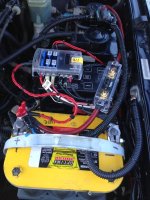
The next step was to prepare the wiring by measuring how far it all needed to go, crimping on some ring connectors and running them to the appropriate locations. As with the write up I used for an example I installed a 125 amp ANL fuse by bolting the fuse holder to the top of the fuse box. The fuse box can still be opened and accessed like normal.
I can't stress this part enough...spend the $10-15 and get a wire crimper. I've tried using channel locks before and it's just not going to do the job of a hammer style crimper.
<a href="http://www.flickr.com/photos/96555314@N02/8861315714/" title="cell phone pics 615 by blueblur19841, on Flickr"><img src="http://farm4.staticflickr.com/3723/8861315714_35a368f731.jpg" width="500" height="375" alt="cell phone pics 615"></a>
<a href="http://www.flickr.com/photos/96555314@N02/8860698337/" title="cell phone pics 618 by blueblur19841, on Flickr"><img src="http://farm3.staticflickr.com/2863/8860698337_32b78aba30.jpg" width="375" height="500" alt="cell phone pics 618"></a>
Next you have to run the wire to where you want it. Going from the battery back:
About 10" of 4 gauge wire from the positive terminal to the ANL fuse
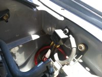
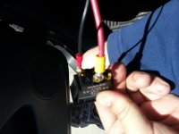
Another 4-5' of 4 gauge to the positive end of the switch installed in the dash (you will need to poke a hole through the grommet to clear the wire)
A ground for the switch
3-4' from the last terminal of the switch, under the body panels and to the underside of the driver seat
<a href="http://www.flickr.com/photos/96555314@N02/8860694485/" title="cell phone pics 620 by blueblur19841, on Flickr"><img src="http://farm9.staticflickr.com/8280/8860694485_54144efed8.jpg" width="500" height="375" alt="cell phone pics 620"></a>
<a href="http://www.flickr.com/photos/96555314@N02/8860692723/" title="cell phone pics 621 by blueblur19841, on Flickr"><img src="http://farm8.staticflickr.com/7325/8860692723_7001a73aba.jpg" width="500" height="375" alt="cell phone pics 621"></a>
<a href="http://www.flickr.com/photos/96555314@N02/8861299786/" title="cell phone pics 622 by blueblur19841, on Flickr"><img src="http://farm6.staticflickr.com/5339/8861299786_e120db5dbf.jpg" width="500" height="375" alt="cell phone pics 622"></a>
<a href="http://www.flickr.com/photos/96555314@N02/8860688873/" title="cell phone pics 623 by blueblur19841, on Flickr"><img src="http://farm4.staticflickr.com/3791/8860688873_7de6e2cbd0.jpg" width="500" height="375" alt="cell phone pics 623"></a>
<a href="http://www.flickr.com/photos/96555314@N02/8861297546/" title="cell phone pics 624 by blueblur19841, on Flickr"><img src="http://farm9.staticflickr.com/8547/8861297546_4a103445be.jpg" width="500" height="375" alt="cell phone pics 624"></a>
<a href="http://www.flickr.com/photos/96555314@N02/8860686827/" title="cell phone pics 625 by blueblur19841, on Flickr"><img src="http://farm8.staticflickr.com/7425/8860686827_aa64c24f61.jpg" width="500" height="375" alt="cell phone pics 625"></a>
<a href="http://www.flickr.com/photos/96555314@N02/8860685417/" title="cell phone pics 626 by blueblur19841, on Flickr"><img src="http://farm9.staticflickr.com/8278/8860685417_59df83006e.jpg" width="375" height="500" alt="cell phone pics 626"></a>
Now we have our fuse box. If I could do it again differently I would have spent the extra money on a fuse box that had the negative distribution panel built in, but I got a seperate panel for the negative lead. PS the paint on the particle board is just rattle can chalk board.
First I lined up the fuse panel to where I wanted it before screwing it on to the board.
<a href="http://www.flickr.com/photos/96555314@N02/8861292766/" title="cell phone pics 627 by blueblur19841, on Flickr"><img src="http://farm8.staticflickr.com/7437/8861292766_f2b3f0c518.jpg" width="375" height="500" alt="cell phone pics 627"></a>
A close up of the inverter I will use before install
<a href="http://www.flickr.com/photos/96555314@N02/8860681109/" title="cell phone pics 628 by blueblur19841, on Flickr"><img src="http://farm4.staticflickr.com/3701/8860681109_89b5ebd36e.jpg" width="500" height="375" alt="cell phone pics 628"></a>
Here is the fuse box after being drilled down. Some cheapo plastic wire holders (not sure what they're called) and zip ties from china freight helps keep everything neat and tidy.
<a href="http://www.flickr.com/photos/96555314@N02/8861289516/" title="cell phone pics 629 by blueblur19841, on Flickr"><img src="http://farm6.staticflickr.com/5343/8861289516_50eface7eb.jpg" width="500" height="375" alt="cell phone pics 629"></a>
Here is the negative distribution panel I will use to keep everything tidy. Eventually this is hooked up to a 8-10" long negative battery cable so that I only need one ground for all the accessories...keeps the rat's nest at bay.
<a href="http://www.flickr.com/photos/96555314@N02/8860677595/" title="cell phone pics 630 by blueblur19841, on Flickr"><img src="http://farm9.staticflickr.com/8279/8860677595_26a835d2eb.jpg" width="500" height="375" alt="cell phone pics 630"></a>
Make sure you tin and solder any wires together if you need some more slack. This goes to my CB mounted in the dash.
<a href="http://www.flickr.com/photos/96555314@N02/8861285002/" title="cell phone pics 631 by blueblur19841, on Flickr"><img src="http://farm8.staticflickr.com/7407/8861285002_1a70b280bb.jpg" width="500" height="375" alt="cell phone pics 631"></a>
<a href="http://www.flickr.com/photos/96555314@N02/8861320442/" title="cell phone pics 612 by blueblur19841, on Flickr"><img src="http://farm4.staticflickr.com/3812/8861320442_6ed3dbdb03.jpg" width="500" height="375" alt="cell phone pics 612"></a>
Here's the same bundle a little futher along
<a href="http://www.flickr.com/photos/96555314@N02/8861279672/" title="cell phone pics 633 by blueblur19841, on Flickr"><img src="http://farm8.staticflickr.com/7298/8861279672_168fc5081f.jpg" width="500" height="375" alt="cell phone pics 633"></a>
And that battery cable we talked about earlier just reaches the rear seat bolt on the transmission tunnel. I had to bore out the hole a tiny bit...a dremmel or drill press will come in handy here, but a circular file will do the trick too.
<a href="http://www.flickr.com/photos/96555314@N02/8861272704/" title="cell phone pics 636 by blueblur19841, on Flickr"><img src="http://farm9.staticflickr.com/8539/8861272704_8959dd81e2.jpg" width="500" height="375" alt="cell phone pics 636"></a>
And here is the ground wire install. You will need to bend back the lead a tiny bit to make it fit the contour of the seat bracket, but this is an easy task. Just clamp down the very end of it to get some leverage and bend as necessary.
<a href="http://www.flickr.com/photos/96555314@N02/8861270564/" title="cell phone pics 637 by blueblur19841, on Flickr"><img src="http://farm3.staticflickr.com/2811/8861270564_0f19e9f7ce.jpg" width="500" height="375" alt="cell phone pics 637"></a>
Last step is optional. I wanted a more standard style terminal so I bought these at my local west marine. Here they are installed. Again, the dremmel is your friend here because I needed to bore out the ring connectors to make them slip on terminals. You should also install a beefier ground regardless of whether or not you change the battery terminals out.
<a href="http://www.flickr.com/photos/96555314@N02/8860657597/" title="cell phone pics 639 by blueblur19841, on Flickr"><img src="http://farm8.staticflickr.com/7313/8860657597_d260664d78.jpg" width="500" height="375" alt="cell phone pics 639"></a>
Hope you guys like this write up and feel free to give me any feedback if you have a recommendations. Until then I'll see you at the next one...my shot shocks are a good excuse to do a toytect life kit.
4Runners.org- Installing a Fused Distribution Box
Here is my spin on this build.
The first step was deciding where I wanted my fuse box and negative distribution panel to be...after some thought the path of least resistance seemed preferable. I uninstalled the 12 CD changer (that doesn't work with my updated cd player any how) and used it as a template to cut out some particle board.
<a href="http://www.flickr.com/photos/96555314@N02/8860710259/" title="cell phone pics 613 by blueblur19841, on Flickr"><img src="http://farm4.staticflickr.com/3827/8860710259_90b2e5ee28.jpg" width="500" height="375" alt="cell phone pics 613"></a>
The next step was to prepare the wiring by measuring how far it all needed to go, crimping on some ring connectors and running them to the appropriate locations. As with the write up I used for an example I installed a 125 amp ANL fuse by bolting the fuse holder to the top of the fuse box. The fuse box can still be opened and accessed like normal.
I can't stress this part enough...spend the $10-15 and get a wire crimper. I've tried using channel locks before and it's just not going to do the job of a hammer style crimper.
<a href="http://www.flickr.com/photos/96555314@N02/8861315714/" title="cell phone pics 615 by blueblur19841, on Flickr"><img src="http://farm4.staticflickr.com/3723/8861315714_35a368f731.jpg" width="500" height="375" alt="cell phone pics 615"></a>
<a href="http://www.flickr.com/photos/96555314@N02/8860698337/" title="cell phone pics 618 by blueblur19841, on Flickr"><img src="http://farm3.staticflickr.com/2863/8860698337_32b78aba30.jpg" width="375" height="500" alt="cell phone pics 618"></a>
Next you have to run the wire to where you want it. Going from the battery back:
About 10" of 4 gauge wire from the positive terminal to the ANL fuse
Another 4-5' of 4 gauge to the positive end of the switch installed in the dash (you will need to poke a hole through the grommet to clear the wire)
A ground for the switch
3-4' from the last terminal of the switch, under the body panels and to the underside of the driver seat
<a href="http://www.flickr.com/photos/96555314@N02/8860694485/" title="cell phone pics 620 by blueblur19841, on Flickr"><img src="http://farm9.staticflickr.com/8280/8860694485_54144efed8.jpg" width="500" height="375" alt="cell phone pics 620"></a>
<a href="http://www.flickr.com/photos/96555314@N02/8860692723/" title="cell phone pics 621 by blueblur19841, on Flickr"><img src="http://farm8.staticflickr.com/7325/8860692723_7001a73aba.jpg" width="500" height="375" alt="cell phone pics 621"></a>
<a href="http://www.flickr.com/photos/96555314@N02/8861299786/" title="cell phone pics 622 by blueblur19841, on Flickr"><img src="http://farm6.staticflickr.com/5339/8861299786_e120db5dbf.jpg" width="500" height="375" alt="cell phone pics 622"></a>
<a href="http://www.flickr.com/photos/96555314@N02/8860688873/" title="cell phone pics 623 by blueblur19841, on Flickr"><img src="http://farm4.staticflickr.com/3791/8860688873_7de6e2cbd0.jpg" width="500" height="375" alt="cell phone pics 623"></a>
<a href="http://www.flickr.com/photos/96555314@N02/8861297546/" title="cell phone pics 624 by blueblur19841, on Flickr"><img src="http://farm9.staticflickr.com/8547/8861297546_4a103445be.jpg" width="500" height="375" alt="cell phone pics 624"></a>
<a href="http://www.flickr.com/photos/96555314@N02/8860686827/" title="cell phone pics 625 by blueblur19841, on Flickr"><img src="http://farm8.staticflickr.com/7425/8860686827_aa64c24f61.jpg" width="500" height="375" alt="cell phone pics 625"></a>
<a href="http://www.flickr.com/photos/96555314@N02/8860685417/" title="cell phone pics 626 by blueblur19841, on Flickr"><img src="http://farm9.staticflickr.com/8278/8860685417_59df83006e.jpg" width="375" height="500" alt="cell phone pics 626"></a>
Now we have our fuse box. If I could do it again differently I would have spent the extra money on a fuse box that had the negative distribution panel built in, but I got a seperate panel for the negative lead. PS the paint on the particle board is just rattle can chalk board.
First I lined up the fuse panel to where I wanted it before screwing it on to the board.
<a href="http://www.flickr.com/photos/96555314@N02/8861292766/" title="cell phone pics 627 by blueblur19841, on Flickr"><img src="http://farm8.staticflickr.com/7437/8861292766_f2b3f0c518.jpg" width="375" height="500" alt="cell phone pics 627"></a>
A close up of the inverter I will use before install
<a href="http://www.flickr.com/photos/96555314@N02/8860681109/" title="cell phone pics 628 by blueblur19841, on Flickr"><img src="http://farm4.staticflickr.com/3701/8860681109_89b5ebd36e.jpg" width="500" height="375" alt="cell phone pics 628"></a>
Here is the fuse box after being drilled down. Some cheapo plastic wire holders (not sure what they're called) and zip ties from china freight helps keep everything neat and tidy.
<a href="http://www.flickr.com/photos/96555314@N02/8861289516/" title="cell phone pics 629 by blueblur19841, on Flickr"><img src="http://farm6.staticflickr.com/5343/8861289516_50eface7eb.jpg" width="500" height="375" alt="cell phone pics 629"></a>
Here is the negative distribution panel I will use to keep everything tidy. Eventually this is hooked up to a 8-10" long negative battery cable so that I only need one ground for all the accessories...keeps the rat's nest at bay.
<a href="http://www.flickr.com/photos/96555314@N02/8860677595/" title="cell phone pics 630 by blueblur19841, on Flickr"><img src="http://farm9.staticflickr.com/8279/8860677595_26a835d2eb.jpg" width="500" height="375" alt="cell phone pics 630"></a>
Make sure you tin and solder any wires together if you need some more slack. This goes to my CB mounted in the dash.
<a href="http://www.flickr.com/photos/96555314@N02/8861285002/" title="cell phone pics 631 by blueblur19841, on Flickr"><img src="http://farm8.staticflickr.com/7407/8861285002_1a70b280bb.jpg" width="500" height="375" alt="cell phone pics 631"></a>
<a href="http://www.flickr.com/photos/96555314@N02/8861320442/" title="cell phone pics 612 by blueblur19841, on Flickr"><img src="http://farm4.staticflickr.com/3812/8861320442_6ed3dbdb03.jpg" width="500" height="375" alt="cell phone pics 612"></a>
Here's the same bundle a little futher along
<a href="http://www.flickr.com/photos/96555314@N02/8861279672/" title="cell phone pics 633 by blueblur19841, on Flickr"><img src="http://farm8.staticflickr.com/7298/8861279672_168fc5081f.jpg" width="500" height="375" alt="cell phone pics 633"></a>
And that battery cable we talked about earlier just reaches the rear seat bolt on the transmission tunnel. I had to bore out the hole a tiny bit...a dremmel or drill press will come in handy here, but a circular file will do the trick too.
<a href="http://www.flickr.com/photos/96555314@N02/8861272704/" title="cell phone pics 636 by blueblur19841, on Flickr"><img src="http://farm9.staticflickr.com/8539/8861272704_8959dd81e2.jpg" width="500" height="375" alt="cell phone pics 636"></a>
And here is the ground wire install. You will need to bend back the lead a tiny bit to make it fit the contour of the seat bracket, but this is an easy task. Just clamp down the very end of it to get some leverage and bend as necessary.
<a href="http://www.flickr.com/photos/96555314@N02/8861270564/" title="cell phone pics 637 by blueblur19841, on Flickr"><img src="http://farm3.staticflickr.com/2811/8861270564_0f19e9f7ce.jpg" width="500" height="375" alt="cell phone pics 637"></a>
Last step is optional. I wanted a more standard style terminal so I bought these at my local west marine. Here they are installed. Again, the dremmel is your friend here because I needed to bore out the ring connectors to make them slip on terminals. You should also install a beefier ground regardless of whether or not you change the battery terminals out.
<a href="http://www.flickr.com/photos/96555314@N02/8860657597/" title="cell phone pics 639 by blueblur19841, on Flickr"><img src="http://farm8.staticflickr.com/7313/8860657597_d260664d78.jpg" width="500" height="375" alt="cell phone pics 639"></a>
Hope you guys like this write up and feel free to give me any feedback if you have a recommendations. Until then I'll see you at the next one...my shot shocks are a good excuse to do a toytect life kit.
Attachments
Last edited: