Agent_Outside: Adventures in a 4Runner Limited

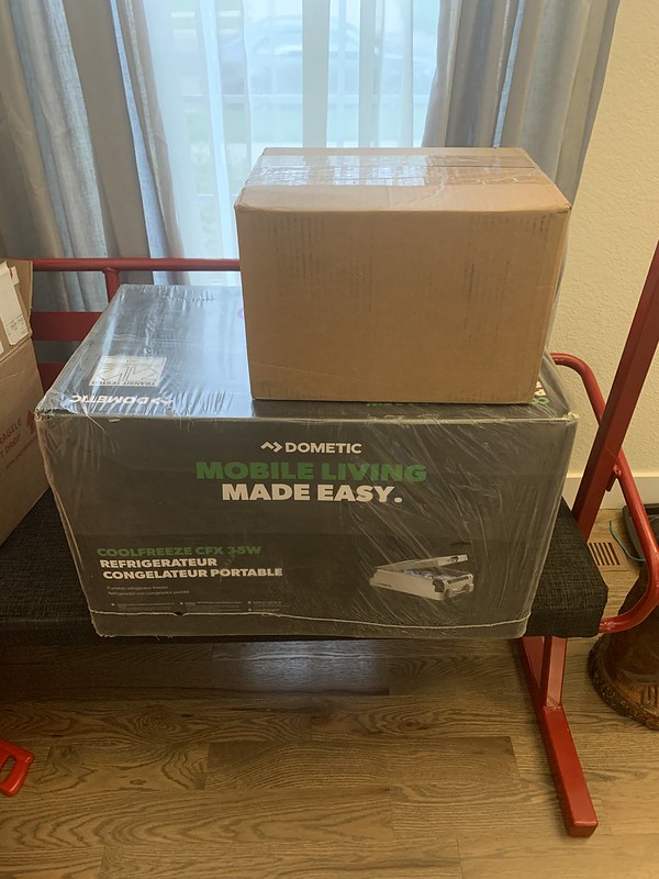
48683536917_5c54414e4d_z.jpg


48683363256_0b3552989c_c.jpg


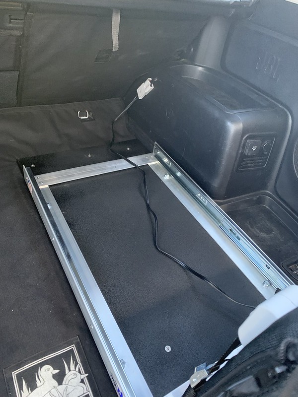
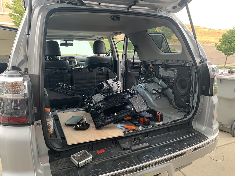
Running wiring and planning out a slide mount.
48683363496_54aa0e8752_c.jpg


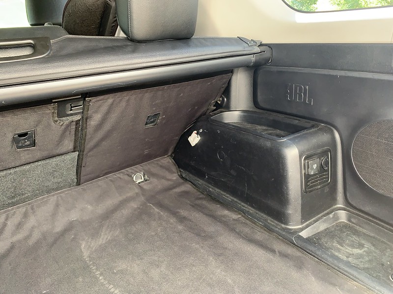
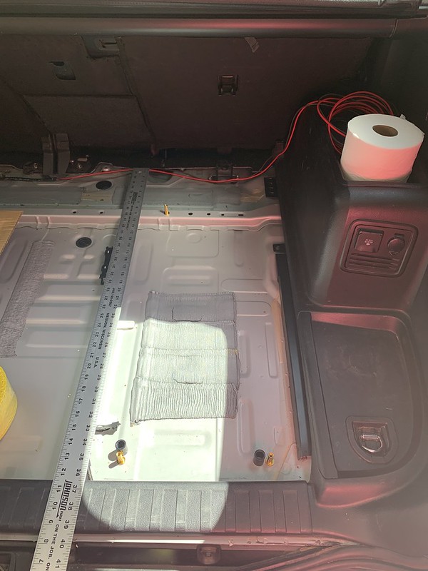
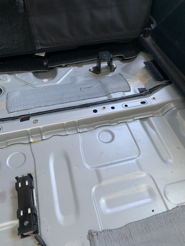
I only have 3 rivnuts on hands so I had to order more but here's the plan. I made a cut a board out of 1/2" birch plywood and shaped it slightly to fit snug up against the passenger side trim. I'm going to put 2 or 3 rivnuts in that crossbar to mount th front of the board. I verified its open under neight the bod so I'll put 2 or 3 more in the back along with metal spacers. I'll cut out holes in the styrofoam layer for the spacer to pass through. I cut the insulation off the underside of the trunk carpet where the board will sit to reduce the height a little bit. Right now I'm still waiting on the fridge slide to continue, its held up being shipped out of FL because of hurricane Dorian causing problems. Once the board is mounted I'll line up the slide to have it as far forward and the side as I can without anything hitting anything. When the mounting is figured out I'm going to use pronged t nuts inder the board to mount the slide from the top. I'd trim down the board as much as possible then Bedliner the whole board to keep it protected and waterproof. With this setup when I take it out for ski season its 4 quick bolts to remove the side and no other hassle.

It should right about here, it'll still clear the privacy cover.
48683363526_e7be162d99_c.jpg


I got the wiring almost buttoned up yesterday. Its ran, it's grounded, and I put some temporary terminals on it to just to turn it on so I could verify the wiring. Dometic has a hardware socket kit thats 25 feet of 10 gauge wire, seeing as I'm running one of the smaller fridges and my run of wire is only about 17 feet or so I opted to go with 12 awg. the temporary hook up was to verify the wire is gauged ok to not impede function. As the fridge compressor starts the max voltage drop on startup is right around .28 volts, that'll work fine. 0.0 is ideal but not worth running like 6 or 8 awg. The performance will be just fine, the one potential concern is the battery protection could kick in earlier if it thinks the battery is lower than it is because of a voltage drop. But, I have everything aftermarket running through a low voltage disconnect right at the second battery so I don't need to utilize the fridges internal battery protection.

I realize I didn't take many pictures, I'll try to grab a few more today, especially if I finish up the wiring.
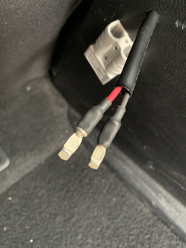
 
I went out of town for a few days and then got sick. Today I finished up the car side wiring. Still waiting for the slide to move forward from here. It should get delivered Thursday, we’ll see how much I can get done before I go back out of town again.

48712336241_282b9862e6_c.jpg


48712003923_0789fbb1f0_c.jpg


48712337371_136fdd134e_c.jpg
 
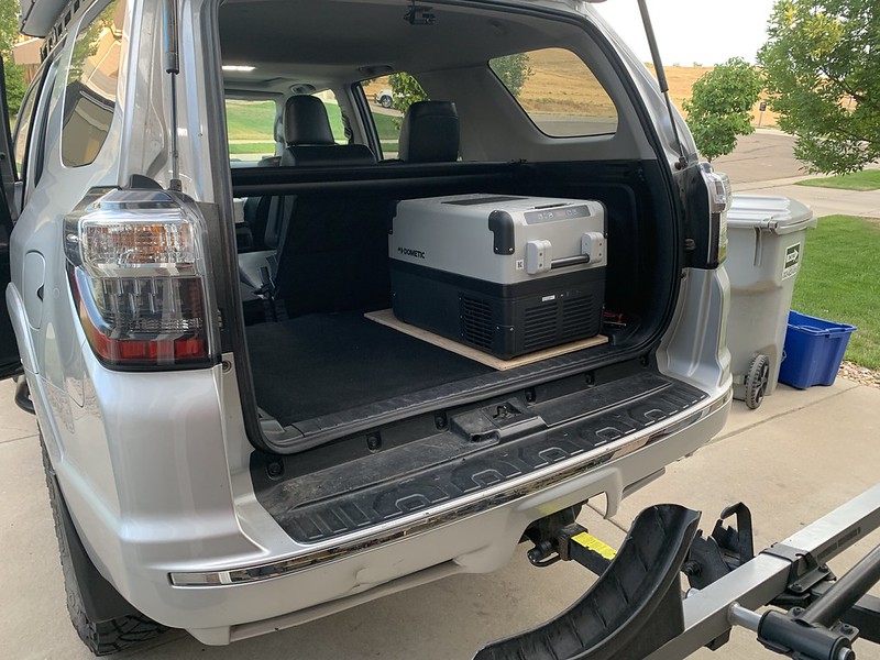
I got the fridge install finished.


I was kinda planning out the space. I didnt have enough rivnuts on hand so I had to order more but this was the gist of it. I wanted to to do 3 rivnuts along the brace and 2 towards the back with spacers.

48683676788_fe556386a2_c.jpg


Rivnuts installed
48733437761_421cfbcf69_c.jpg


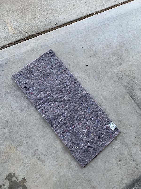
I cut off the insulation from the underside of the carpet where the board would sit to give it a more solid surface on the hard foam under the carpet and bring the overall height down a hair.
48733481067_f7a2d63a1e_c.jpg


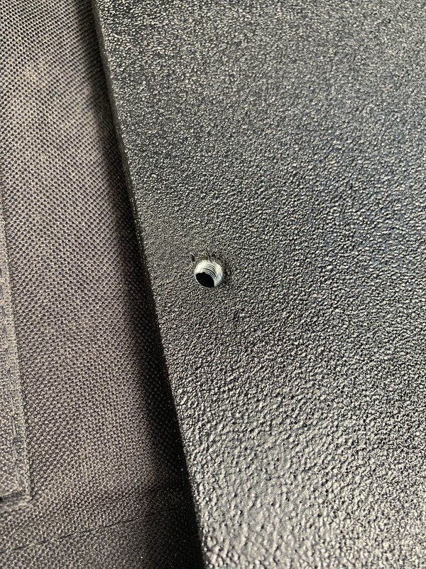
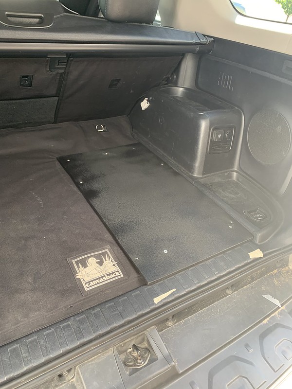
I countersunk the 5 holes to mount the board the to the floor of the body so it sits flat and flush and for the side to attached I used pronged t nuts that were glued and hammered in. Then I coated the board with black primer/sealer scuffed it up and hit it with 4 coats of bedliner.
48733438101_fda6460b0c_c.jpg


I cut holes in the thick foam for the spacers to slide in, then I cut small holes in the trunk carpet for the bolts to pass through and I cut out a scetion of the Canvas Back liner so it can just be permantly sandwiched in there and mounted up the board. Its supper solid, it doesnt flex or move.
48733106868_63a76a87b8_c.jpg


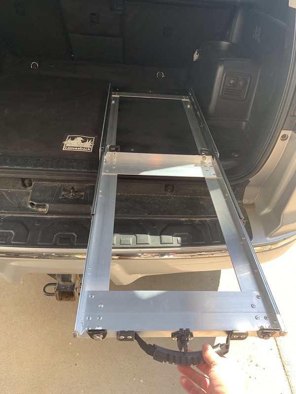
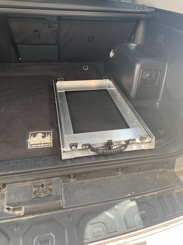
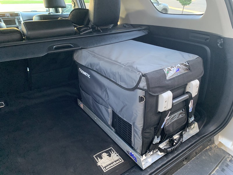
From there I bolted up the DFG Offroad slide.
48733617317_53b7185373_c.jpg


48733437606_ffe79a7b13_c.jpg


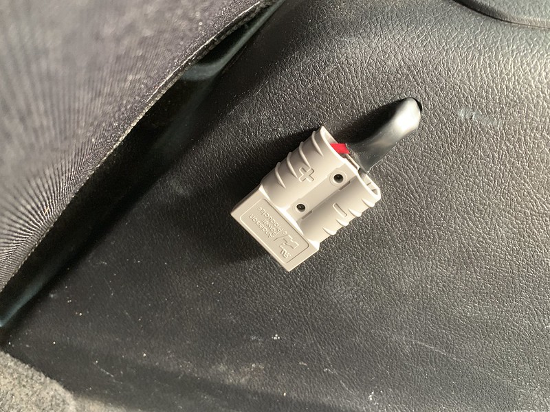
I checked to see how long I'd need the wiring before cutting the 12v plug off and installing an Anderson SB50 connection.
48733480917_669f0ae5d2_c.jpg


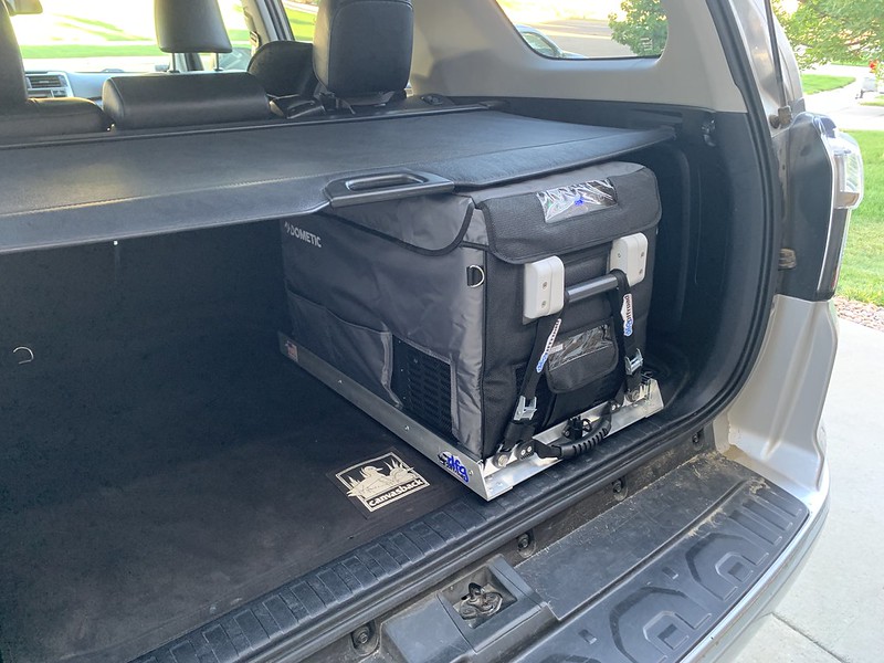
When I was planning everything I was measured known dimensions out with a tape measure and made some assumptions about the unknowns and it was going to be to close to tell if it would fit with the privacy cover or not. I'm happy to say it all came together exactly how I had hoped.

You can retract the cover and the fridge can be opened and closed as it sits. With the cover in place, it can be slid right out and opened.

48733480727_f4b0babd9a_c.jpg


48733480767_f6f485a329_c.jpg


YouTube
 
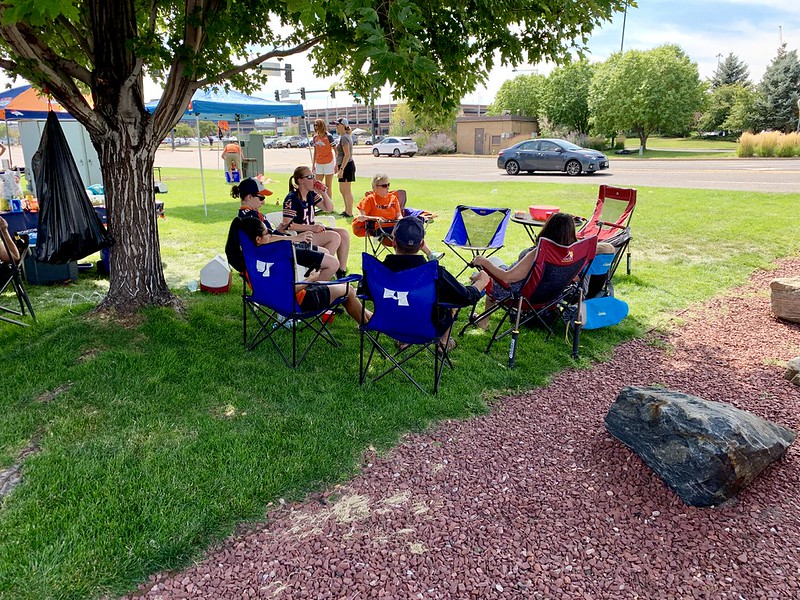
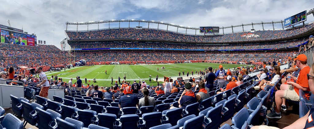
We already got to put the fridge to good use tailgating for the Chicago Bears visit to Denver, they pulled off a win in a thriller.

48751835006_57e4d89046_c.jpg


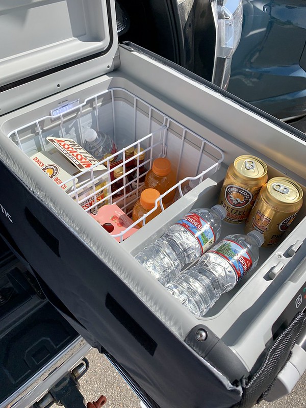
It's so nice having always the perfect temperature drinks ready to go.
48751804731_4aed8dfb9d_c.jpg


48751963127_616c5962c0_c.jpg


48751503603_ba3c45223a_c.jpg


48751480888_d4303a0dd4_c.jpg


48751820406_b660264363_b.jpg


48751765761_0c5ebe57de_c.jpg


48751842946_250e6ec17f_c.jpg
 
It was time for brakes on the 4runner.

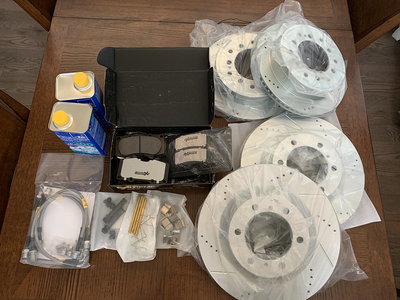
I live in the Colorado mountains, I have some extra weight and bigger tires on the 4Runner, plus I tow from time to time. My brakes don’t have it easy so it was logical to look for an upgrade over stock, especially given the cost of stock pads and rotors. When it comes to parts I always buy OEM or I upgrade. I started researching and decided to go with the Powerstop Z36 brake upgrade. Powerstop recommends that kit for a vehicle with larger than stock tires, added weight, or for towing at least once a year. It's a pretty complete package - pads, rotors, and hardware and on forums and facebook groups, I was seeing a lot of positive reviews and recommendations for it. I also decided to replace the stainless steel brake lines with the kit from Goodridge. A reputable brand, even Tirerack sells them, and their kit was actually for 6 lines, 1 per wheel and the 2 flex lines from the body to rear axle housing. I got high-quality DOT4 fluid and I was good to go.


Everything ready to go.
48821672622_6fba5abbf7_c.jpg


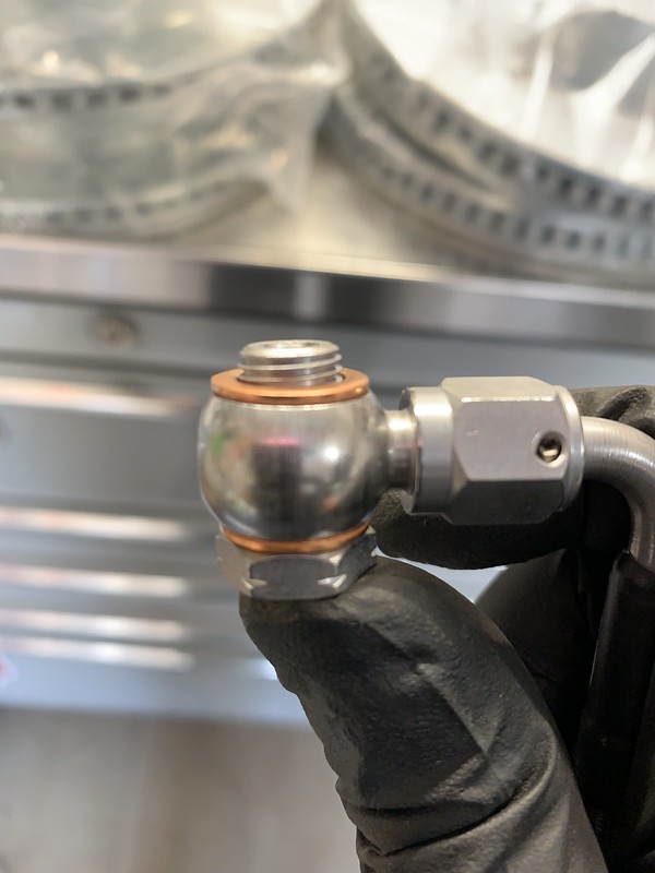
I thought I'd start with the stainless steel lines first. I was matching everything up to make sure it was right and notice a major, MAJOR, problem. The new bolts that came with the new lines to bolt the banjo fitting onto the rear caliper are dangerously undersized. You should have quite a few threads to screw in before you get to the point of collapsing the crush washers... this pile of hot garbage has 2 threads exposed.

This is dangerous, its an accident waiting to happen and there's not a chance in hell I would install this on any vehicle. This is extremely likely to end in catastrophic failure of the brake system. My mind was blown at the level of oversight here.
48821672467_19df58c4d4_c.jpg


So the lines are a bust... we said screw it I'll leave the lines alone for now and we'll just do the brakes.

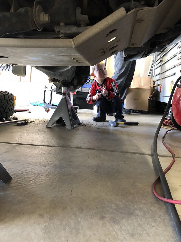
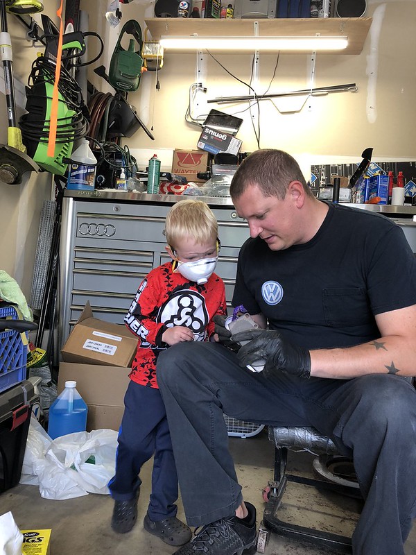
My helper and I started to tear everything down.
48834764293_2f3ec9670b_c.jpg


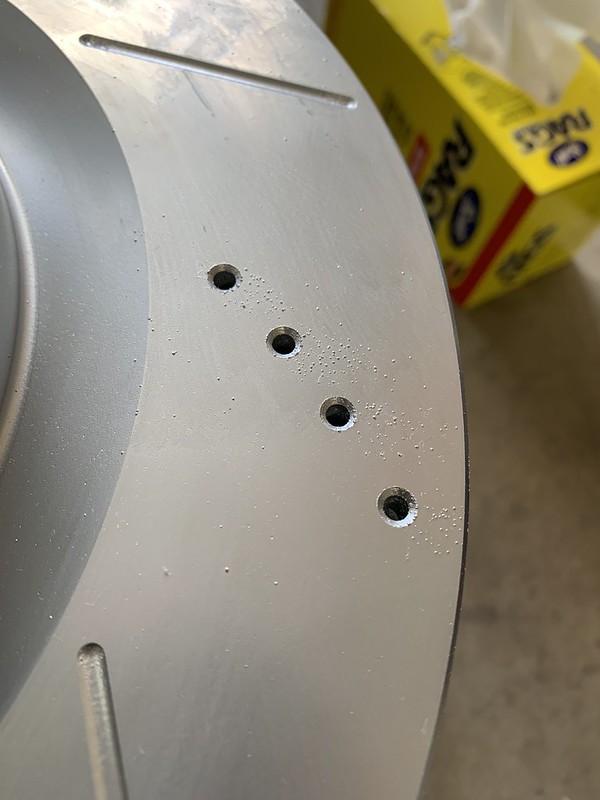
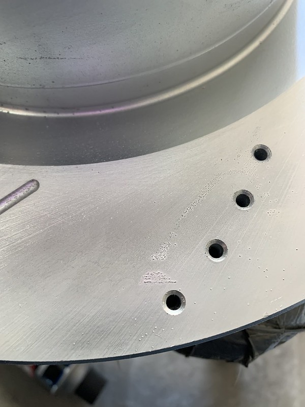
Turns out the Powerstop kit wasnt any better than the brake lines!

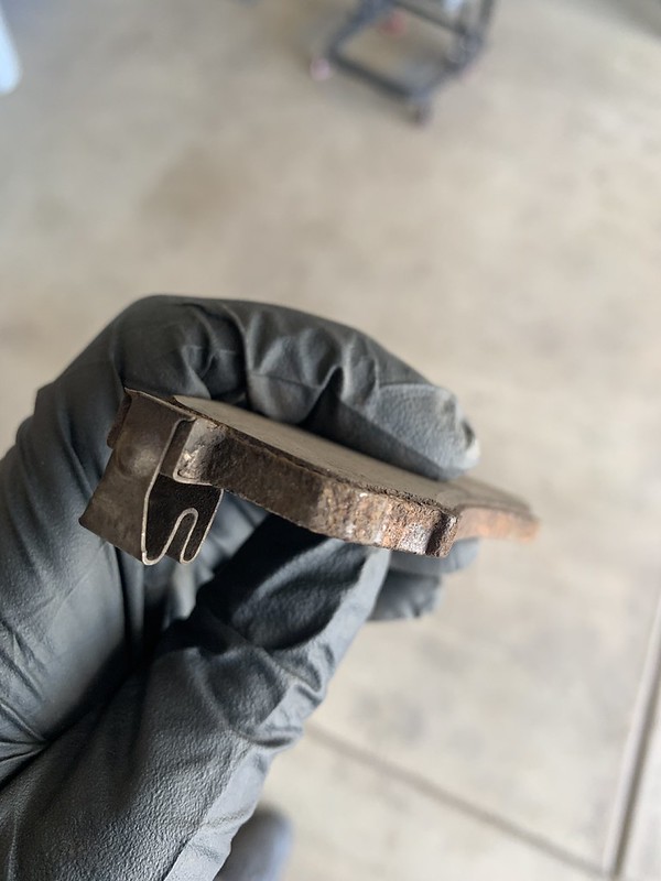
There was all sorts of debris in the zinc coating just waiting to get embedded into the brake pads. I've never seen a worse finish on new brake in my 15 years of working professionally in automotive.
48821672477_9304a6e751_c.jpg


48821672512_96a7e0fe4c_c.jpg


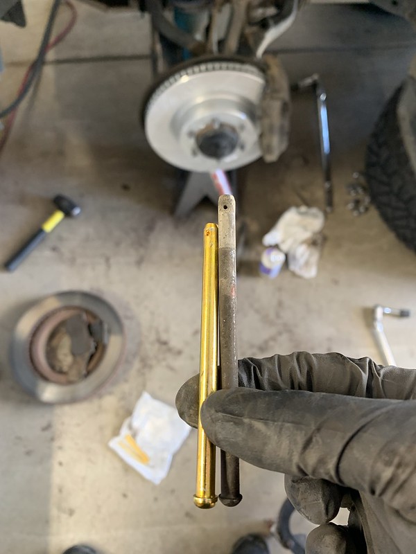
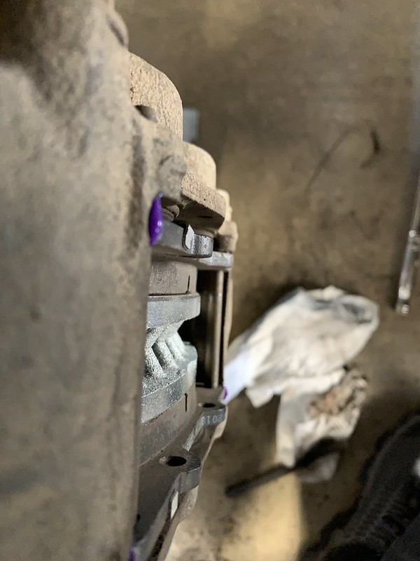
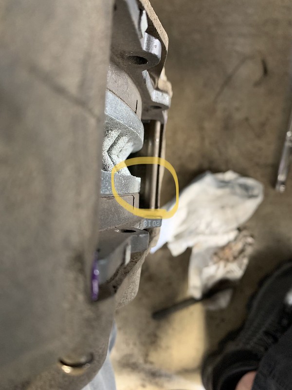
I installed the pads and went to put the caliper pins in, but wait a minute... they aren't long enough to actually come out the back of the caliper.
48821672562_a57be6f960_c.jpg


So I reused the stock hardware to properly secure the pads and found another interesting tidbit.

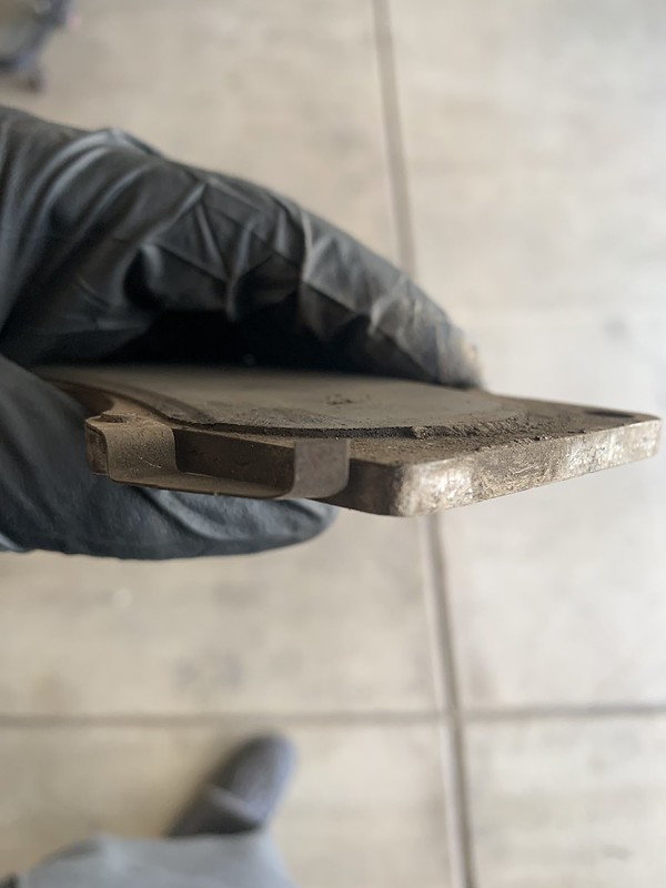
This is how a pad should sit, the friction material stops just short of the edge of the rotor, especially when there a slight chamfer on the edge of the rotor. You want flat surface on flat surface.
48821672697_956325813a_c.jpg


But the inconsistencies in the build quality of the pads left the friction material hanging just a hair over the edge of the rotor. This is not acceptable.
48821672172_c71cc36b76_c.jpg


At that point, I had enough. I said screw all this stupid crap and took one of the over vehicles over to Toyota and just bought all new OEM parts.

I definitely got my money's worth out the old brakes.

Front
48821158813_26727b6b2a_c.jpg


Rear
48821516676_2374cf9860_c.jpg


We got the new pads and rotors installed, flushed the brake fluid, and adjusted the parking brake.
48835305202_9f09341405_c.jpg


Because I've seen it asked about a decent amount I decided to take a quick video of how to adjust the parking brake so it grabs strong and stiffens up the parking brake pedal. Hopefully, this can help someone out.

https://www.youtube.com/watch?v=it4BMOrM41g&feature=youtu.be
 
Hey there quick question for you. What is the purpose of the blue sea since you have the redarc? Isn't the redarc handling all the switching for charging? Also, why circuit breakers instead of fuses?

Thanks!

ben
 
Hey there quick question for you. What is the purpose of the blue sea since you have the redarc? Isn't the redarc handling all the switching for charging? Also, why circuit breakers instead of fuses?

Thanks!

ben

The 2 components serve different purposes. The Redarc does not do any switching, the batteries are never connected to each other. The starter battery is charged via the alternator, the redarc then uses the starter battery as the power input to the redarc which operates as a smart charger for the secondary battery. The blue sea is a low voltage disconnect between the secondary battery and the power distribution module that powers every single non OEM thing IÂ’ve added. If the voltage of the secondary battery gets to low, the blue sea interrupts power to the PDM to avoid killing (and in turn damaging) the secondary battery. With my setup it will turn off all aftermarket loads and accessories before killing the secondary battery and thereÂ’s no way for any of it to affect the starter battery so the truck will always start, and when it does the redarc will start charging the secondary battery using whatever charge profile is the most beneficial to the health of the battery.

Circuit breakers and fuses serve the same function, they open the circuit if there is to much amperage is being pulled. Circuit breakers are just simply a better version of a fuse, they are resettable, reusable, the circuit can be open or closed with a press of a button, and you donÂ’t need anything if it goes off. If youÂ’re out somewhere and you trip a breaker you can reset it without needing to find a replacement fuse. LetÂ’s say a wire rubs through the insulation and it shorts to ground over big bumps. You could reset a breaker every time it happens until your somewhere you can fix it. With a fuse youÂ’d have to have spares and keep replacing them. The disadvantage is that you canÂ’t change the load rating, a breaker is what it is whereas a fuse can swapped out for different sizes, but realistically thatÂ’s not something you should be doing anyway. You donÂ’t fuse to protect the component, you fuse to protect the circuit. The appropriate sized fuse is one that will pop before the weakest link in the system will pull enough amperage to start a fire. At the end of the day a way to open an overloaded circuit is a safety item you need to have, a breaker is just a more expensive nicer version of a fuse but either one will do the job.

Let me know if you have any other questions.
 
Hey buddy. Nice rig and great photos! Quick question: what is the purpose of the Blue Sea low voltage disconnect in your dual battery setup? Won't the Redarc cover that if you're discharging the battery? I'm working on a similar setup and wanted to make sure I'm not missing something!

Cheers!

b
e
n
 
Hey buddy. Nice rig and great photos! Quick question: what is the purpose of the Blue Sea low voltage disconnect in your dual battery setup? Won't the Redarc cover that if you're discharging the battery? I'm working on a similar setup and wanted to make sure I'm not missing something!

Cheers!

b
e
n

I explained the functionality of the components in the post prior to yours (last post on the previous page). The redarc has nothing to do with discharging batteries, it’s a battery charger.
 
BlueSea Dip Switch settings?

Hey there.Ben in Atlanta here again. I've almost completed my dual battery setup and aside from using fuses instead of circuit breakers, it's very similar to yours. I'm having one problem though that I can't seem to diagnose. I thought you might have some insight since you're using the BlueSea 7615 LVD also.

No matter what I set the dip switch settings at, I can't get the BlueSea to pass voltage. Battery is showing 12.68 volts and I'm trying to set up the LVD to strictly be an LVD, no timer or ignition/alternator sensing, etc. But, I can't get it to open. Any suggestions? Any idea what your dip switch settings were? I know that's a longshot to remember but thought I'd ask.

Cheers.

b
e
n
 
Hey there.Ben in Atlanta here again. I've almost completed my dual battery setup and aside from using fuses instead of circuit breakers, it's very similar to yours. I'm having one problem though that I can't seem to diagnose. I thought you might have some insight since you're using the BlueSea 7615 LVD also.

No matter what I set the dip switch settings at, I can't get the BlueSea to pass voltage. Battery is showing 12.68 volts and I'm trying to set up the LVD to strictly be an LVD, no timer or ignition/alternator sensing, etc. But, I can't get it to open. Any suggestions? Any idea what your dip switch settings were? I know that's a longshot to remember but thought I'd ask.

Cheers.

b
e
n


Sorry just now saw this, do you have the ground hooked up? I needs power and ground for it to register voltage
 
This is incredible. We're contemplating making the move from Michigan to Colorado in the next year or two. This gives me so much inspiration.

Sent from my Pixel 4 XL using Tapatalk
 
The load side of the relay is fused power on one side and the power wire for the fogs connected to the other side. It’s a simple mod if you have a wiring diagram. That was the first mod I did, I didn’t document specifically which wires in the vehicle I used.


Is there any chance you can find out what power wire color code was used on which harness? I have been stuck in my cabin testing wires with a test light trying to figure out which line feeds fogs so I can connect relay! Going nuts. Antmans doesn't match up to my 2014
 

Members online

Forum statistics

Threads
278,312
Messages
3,554,087
Members
248,016
Latest member
Advally Service

Trending content

Back
Top