AOB switch and Black Oak lights wiring

Cutty01 I'm still trying to make it work can you confirm that the diagram that I am posting right now is correct ? also the red wire coming out of the relay on the harness goes where?....

I realize its probably easy to figure out I just don't want to mess up anything ...

thanks (again)
Erick.

What's on the other end of the Black wire and Red wire with the eyelets?
The Light Bar?
 
What's on the other end of the Black wire and Red wire with the eyelets?
The Light Bar?

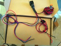
Saker, on the other end of the wires with the eyelets is the relay.
I am including a picture .
 

Attachments

  • IMG_2609a.jpg
    IMG_2609a.jpg
    123.8 KB · Views: 3,636
I am sorry, I haven't worked with particular harness before and you are trying to do multiple things (powered by ignition and dimming) that make the wiring a little more complex. From the looks of things, the harness you are showing provides power and ground to the switch that came with it by using power and ground directly from the battery so you don't have to splice into the factory wiring. I can't confirm this as the shrink tubing around the relay adapter is hiding the wiring. If you just wanted to use the AOB switch for simple off/on you could just directly connect the red and black switch wires from the LED harness to the green and black wires of the AOB switch and then connect the blue trigger wire to the red wire of the AOB switch, but that's not your intent.


With the setup we are describing (power from ignition and dimming), I am guessing you won't need the red and black switch wire from the LED harness and you only need the blue wire to trigger the relay. You could also rip out the adapter connected to the relay and direct wire the way have described to the pins on the relay. But I am totally guessing. Because you are splicing into the factory harness and the AOB switches have multiple wiring diagrams, I don't want to lead you wrong and fry something. I am going to let [MENTION=103267]Saker[/MENTION] help you from here. I also sent a PM to [MENTION=83083]rigtec[/MENTION] for a second opinion and to join this discussion. From his posts he seems like a wiring expert.
 
Last edited:
I'm in the same boat as [MENTION=128325]cutty01[/MENTION].
Never worked with this type of harness, doing multiple things.

You can try to wire it as cutty01 described.
 
I'm in the same boat as [MENTION=128325]cutty01[/MENTION].
Never worked with this type of harness, doing multiple things.

You can try to wire it as cutty01 described.

IT WORKS.....!!!!!!
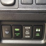
I wired it the way Cutty01 said (ignore the black and red wires coming out of the relay ) I used the blue trigger wire only ...I now get ignition only , dimmer and on off LED.
thanks Cutty01 , Saker and a few more !
Erick.
 
results:
10 inch light bar from Black Oak , 1 pair of 2 inch 40 W pods /spots from Black Oak amber covers....AOB switches .
 

Attachments

  • IMG_2616a.jpg
    IMG_2616a.jpg
    134.9 KB · Views: 5,110
  • lightbar1.jpg
    lightbar1.jpg
    131.3 KB · Views: 2,912
IT WORKS.....!!!!!!
I wired it the way Cutty01 said (ignore the black and red wires coming out of the relay ) I used the blue trigger wire only ...I now get ignition only , dimmer and on off LED.
thanks Cutty01 , Saker and a few more !
Erick.

Ahhh, success! That's a beautiful thing; so glad that it worked out!
 
IT WORKS.....!!!!!!
I wired it the way Cutty01 said (ignore the black and red wires coming out of the relay ) I used the blue trigger wire only ...I now get ignition only , dimmer and on off LED.
thanks Cutty01 , Saker and a few more !
Erick.

results:
10 inch light bar from Black Oak , 1 pair of 2 inch 40 W pods /spots from Black Oak amber covers....AOB switches .

I like the results and the look! :thumb3:
 
Just for a little added clarity...

The Black wire (with loop) goes from the NEG battery terminal to the NEG LED ground terminal, the relay coil, and then to the switch. The Red wire (with loop) goes from the POS battery terminal to the #30 common terminal on the relay (common is just a term that means that the power is available to feed either the Normally Opened (87), or the Normally closed (87A) terminals on the relay) then to the switch (Power-in terminal). The BLUE wire goes from the relay trigger (Positive coil terminal) and to the switch to be energized whenever the switch is turned on to trigger the relay!

That's it gents; nothing spooky or esoteric! Now your AOB switch has two extra wires on it; an option just in case you desire the switch face to light up with the rest of the switches on your dash when your parking lights are on... which is why a lot of us like these switches so much, cuz they're so versatile. Just a note: If you want the switches etched face to light up and to dim with the other factory switches, you'll need to tap the courtesy circuit lighting on one of the other dash switches... Green is HOT, Gray is Ground; and is the wire that causes the others to dim with the dial; they'll be no dimming without tapping that gray wire!... hope this helps,

Best to you!
 
Last edited:
[MENTION=128325]cutty01[/MENTION] and [MENTION=83083]rigtec[/MENTION]

I have the same setup as [MENTION=140360]airbusa380[/MENTION], except mine's a roughcountry light and the wires that go from its relay to its on/off switch are black, white and blue instead of airbus's red black and blue. I wired the red AOB wire to the Blue Roughcountry switch wire and nothing, however if I touch the red and blue to the white it'll turn on regardless of whether the key is turned, but I have no control over the switch. Obviously I won't connect the black wire to the group, because that would be bad. I do however have the led's working in the AOB switch itself, and they dim with the headlights. Here's what the roughcountry switch from the relay looks like, I took the cover off it.
62EFD92A-294D-4560-99DB-5103FD2C3FFA.jpg~original
 
Last edited:
Hi Paragon1,

We will definitely need a bit more information to do this right. Either flip the switch upside down so we can see the trace pattern (just another form of plotting the scheme w/out any paperwork), or cut the OEM switch off and let-us see the other end near relay and identify your wires that way. The AOB switch should have come with a wiring diagram so maybe you could post that too!

Cheers
 
Hi Paragon1,

We will definitely need a bit more information to do this right. Either flip the switch upside down so we can see the trace pattern (just another form of plotting the scheme w/out any paperwork), or cut the OEM switch off and let-us see the other end near relay and identify your wires that way. The AOB switch should have come with a wiring diagram so maybe you could post that too!

Cheers

Sorry bout that, should've sent a more thorough pic. The wiring diagram are is identical to the ones posted earlier. The only thing I'm not getting is the trigger to activate the relay to power the lights. The wires coming from the relay are blue white and black and those are the ones that plug into the OEM switch. I'm thinking I may have gotten a bad switch?
750EF17F-B820-402A-8A53-5E9C7FB93151.jpg~original
 
Sorry bout that, should've sent a more thorough pic. The wiring diagram are is identical to the ones posted earlier. The only thing I'm not getting is the trigger to activate the relay to power the lights. The wires coming from the relay are blue white and black and those are the ones that plug into the OEM switch. I'm thinking I may have gotten a bad switch?

...maybe you could post the relay wiring w/ numbers showing and wire colors; then we can interpret the harness wiring. Then next is the AOB switch. We need the switch color to harness color connection scheme. The more you give us, the easier it will be to get it operating. Rgds!
 
...maybe you could post the relay wiring w/ numbers showing and wire colors; then we can interpret the harness wiring. Then next is the AOB switch. We need the switch color to harness color connection scheme. The more you give us, the easier it will be to get it operating. Rgds!

This is my wiring scheme

Black - Connect to gray factory wire (- dimming)
Blue - Connect to green factory wire (+)
Red - Connect to relay trigger wire (in my case the blue wire coming off the relay) to power the relay when switch is engaged/turned on
Green - Connect to hot lead (ignition source using adapter below to provide power when ignition is on). Reference the pic of the adapter I was advised to use on page 2
 
So it looks like the white wire is a bleed off the the positive power from the battery and the black is ground, which means you have rightly assumed that blue is the trigger.

So lets try to rule out some things.

1. Rule out AOB swtich and tap power from ignition. Connecting the red and black LED harness wires to the battery and using the switch that came with the harness and wired correctly (blk to blk, blu to blu, white to white) does the LED come on?
a. If yes, we know that your battery connections are correct, we know the relay is working, and we know the LED is functioning
b. If no, either you have a bad ground, a bad relay, a bad harness switch, or a bad LED

2. Check tap wiring from fuse box. When the key is turned on and using a voltmeter, do you have 12.x volts? Confirm that when the key is off you have 0 volts.

3. Check the AOB switch w/o tap wiring from fuse box. If you plug the green AOB wire to the harness white wire and the red AOB wire to the blue harness wire, does the LED come on?
a. If yes, you know your AOB switch is working
b. If no, then the AOB switch is faulty or we are using the wrong wiring diagram for the AOB switch you have.

If all the above test are positive it should work exactly how airbusa wired his.

 
Last edited:
So it looks like the white wire is a bleed off the the positive power from the battery and the black is ground, which means you have rightly assumed that blue is the trigger.

So lets try to rule out some things.

1. Rule out AOB swtich and tap power from ignition. Connecting the red and black LED harness wires to the battery and using the switch that came with the harness and wired correctly (blk to blk, blu to blu, white to white) does the LED come on?
a. If yes, we know that your battery connections are correct, we know the relay is working, and we know the LED is functioning
b. If no, either you have a bad ground, a bad relay, a bad harness switch, or a bad LED

2. Check tap wiring from fuse box. When the key is turned on and using a voltmeter, do you have 12.x volts? Confirm that when the key is off you have 0 volts.

3. Check the AOB switch w/o tap wiring from fuse box. If you plug the green AOB wire to the harness white wire and the red AOB wire to the blue harness wire, does the LED come on?
a. If yes, you know your AOB switch is working
b. If no, then the AOB switch is faulty or we are using the wrong wiring diagram for the AOB switch you have.

If all the above test are positive it should work exactly how airbusa wired his.

Doesn't seem to be any power coming from the slot I used in the fuse box. Which is odd because it's the same as the one in this pic.
7D9F6C1E-161B-4C0D-BBCB-ED70E1AE57FE.jpg~original


Then light works when I go by your instructions in section 3. So the problem is the power supply from the fuse box. What's next?
 
Holllld the phone, I need to put a fuse "in" the damn adaptor!!!!! This serves as my public admission to being mentally challenged, or at least observationally challenged....

[MENTION=128325]cutty01[/MENTION], tell me your favorite bottle of reasonably priced scotch and it'll be in the mail. Thanks for the assist!
 
Last edited:
Holllld the phone, I need to put a fuse "in" the damn adaptor!!!!! This serves as my public admission to being mentally challenged, or at least observationally challenged....

[MENTION=128325]cutty01[/MENTION], tell me your favorite bottle of reasonably priced scotch and it'll be in the mail. Thanks for the assist!

Chuckle. I am glad you got it figured it out.

Thank you for your kind gesture. My only ask is that you help another in need just like so many in this forum have helped me.
 

Members online

Forum statistics

Threads
278,316
Messages
3,554,111
Members
248,016
Latest member
Advally Service

Trending content

Back
Top