CCDave's 1987 Turbo 4Runner Build

CCDave

New member
34151007635_e6ea1ca298.jpg" width="500" height="300"


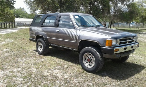
I've had this for a few weeks now and overall it's in good shape thanks the work of FuelInfected.org restoring her back to a daily driver condition. The photo above was taken right after the stripe kit was put, which is why the side mirrors were still off. She needed a lot of TLC and here's a list of what I can remember was done before I got it:
-Replaced A340H Transmission
-Replaced Turbo
-New front calipers
-Replaced steering components
-Replaced several hoses
-Replaced water pump
-Replaced windshield
-Replaced driver power window
-Troubleshoot A/C (bad evaporator)
-Repaired rust
-Painted and added stripe kit
-Reinstalled seats and rest of interior
-etc.

And a list of the known things still to do or look at:
-Replace Heater control valve (Seized)
-Repair Heater switch on Climate Control (busted due to seized control valve)
-Replace power antenna
-Replace evaporator
-Replace shocks
-Inspect differential
-Inspect all hoses
-Clean seat upholstery
-Paint a few interior pieces
-Re-key tailgate cylinder
-New sound system
-Clean and attach emblems/badges

I replaced one of the trans oil cooler lines earlier in the week, it had a slight leak at the fitting on the transmission end. Picked up a new brake line, steel fitting, and tube bender. The line I took out was not original and since it didn't hit all the line hangers I couldn't use it as a guide for the bends on the new line. I straightened a metal hanger and used it to figure out the bends I needed to catch the hangers and then used the hanger as a template.

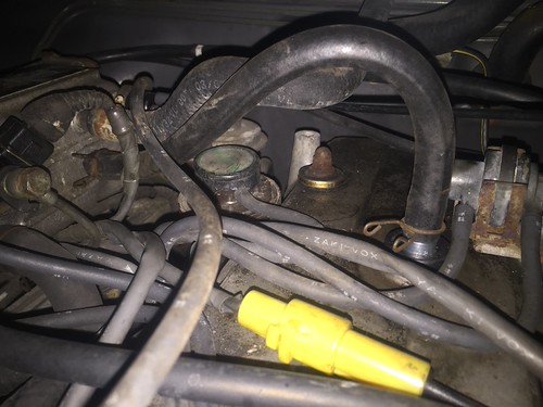
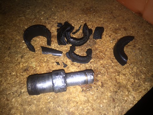
Tonight I replaced the PCV, grommet and hose. Like many others who have done this, the PCV gave a good fight but I finally worked it free. The grommet came off in pieces. The bottom section fell into the valve cover, but I was able to reach into the PCV hole with the needle nose and pull it out.

Old PCV and grommet:
33668428223_c54b9f0342.jpg" width="500" height="375"


New PCV, grommet and hose installed:
34318362142_cf4514982c.jpg" width="500" height="375"
 
Register to hide this ad
B Pillar Badges

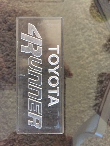
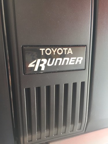
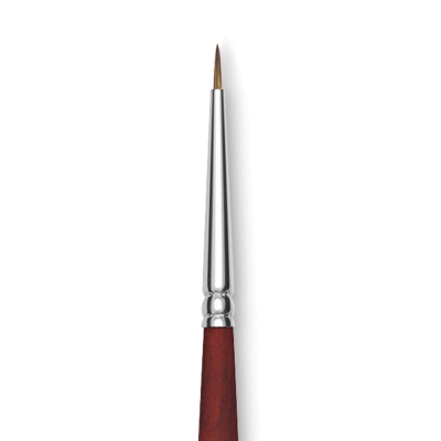
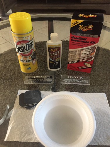
I restored the B pillar badges over the past couple of days and attached them today. To remove the old paint, EasyOff (yellow can) oven cleaner worked real well. It did leave spots of white haze on the front and back of each badge so I used a headlight resto kit on it and that cleared it up. I painted the "TOYOTA" with white Testor's enamel (2 coats), the "4Runner" with DecoArt Dazzling Metalic silver (3 coats) and the back with Testor's gloss black spray paint (2 coats). I used a Spotter style detail artist paintbrush to paint the lettering. Some white and silver paint got on the back surface and I took that off with sandpaper from the headlight resto kit and then painted the back black after taping the sides. I used 3M Molding Tape to attach the badge to the B pillar. Other than a few small cracks on both badges that are interior cracks that can't be sanded down, the badges themselves were in good shape. I decided to go with silver for the "4Runner" lettering instead of the original gold because it matched the silver stripes.

33751697873_c9ce00f9f8.jpg" width="375" height="500"
33719285004_f70bd798f3.jpg" width="375" height="500"
33719284604_90d6222695.jpg" width="375" height="500"

3m-super-strength-molding-tape-03609.jpg
DA070.jpg

06438-1050-1-2ww-m.jpg
 
Last edited:
nice job on refurbishing the emblem

Thanks. Credit goes out to others on this forum and the yota forum that have posted their experiences, tips and tricks. Many have used a gold leaf or silver leaf pen for the "4Runner" text. I went with paint to save $.
 
Door Pull Cup Repair

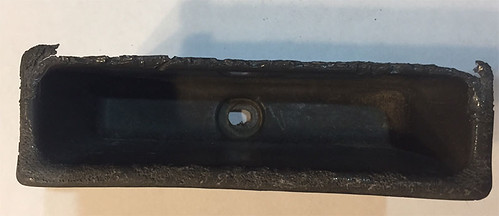
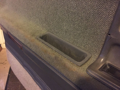
The door pull cups on both doors definitely look their age. Here is the left ...

34555198841_bd19d09e7b.jpg" width="500" height="216"


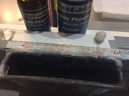
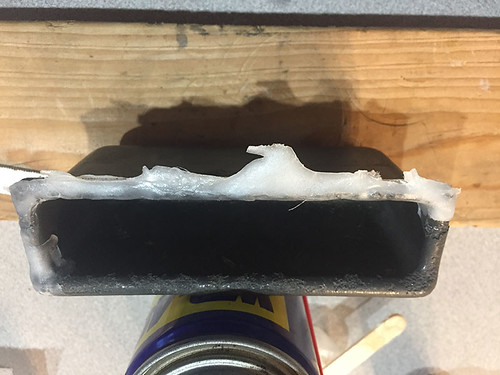
I tossed around a few ideas and decided on a product called Plast-aid to rebuild the front lip. My first attempt was a fail. I thought I could wait until the plastic began to cure to a pliable state and then pull/fold it to the shape I wanted, but it wouldn't stick to the cup. I rigged up a stand to hold the front of the cup against a flat surface so I could pour the semi-liquid plastic along the front edge and gradually shape it as it cured. That worked well and after 10 minutes it began to fully cure.
33875882133_7247ec6bd8.jpg" width="500" height="375"


In 15 minutes I was able to pull it off the stand ...
34555198821_cecc0f6822.jpg" width="500" height="375"


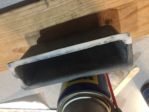
Here it is sanded down ...
34555198741_9915f51b01.jpg" width="500" height="375"


I only had one sheet of used 120 so I didn't get it completely smoothed out, which showed after the first coat of paint ...
33875882073_193246b097.jpg" width="500" height="375"


I'll have to pick up some sand paper so I can finish this one and also repair the right one.
 
Front Rotors, Pads and Wheel Bearings plus reinstall Stabilizer Bar

Installed new Rotors, Pads and Wheel Bearings during the week and today I tackled the 2 stabilizer bolts that were broken off into the frame.

Although these videos are for a slightly different setup than the 1987 4Runner, they along with the manual were a very useful reference for replacing the rotor, wheel bearings and brake pads - https://www.youtube.com/watch?v=FbpCUvh3w9E and https://www.youtube.com/watch?v=GdG_C9Kzrvg.

Old hub attached to new rotor along with new wheel bearing and seal:
34689905304_967cabf3c4.jpg" width="500" height="375" alt="New-Rotor-and-Hub-1small"


Two stabilizer mounting bolts (1 on each side) were broken off and extracting them and reinstalling the bar took several hours that included a couple trips to the store. I first tried a #3 extraction set, but the bolts wouldn't budge and the extractor was close to breaking off. Time for Plan B. I picked up a few drill bits in different sizes and starting with the original hole that I drilled for the extractor, I gradually increased the size of the hole until I could get the Tap in and re-thread it.

Stabilizer Install Instructions:
35531178245_4bb178da37.jpg" width="500" height="274" alt="Install Stabilizer Bar 1987 4Runner Steps"


Tapping new threads for a bracket bolt (m8 x 1.25):
35364019592_0290994bf7.jpg" width="500" height="375" alt="Tap-for-Stabilizer-bolt-small


Next on my list is replace the climate controls with one that come off an 89 and replace the AC Evaporator. On the 89 unit, Toyota replaced the plastic fastener that attaches the Heat switch to the climate control assembly with a metal fastener, making it more durable. I also just found out the evaporator on my 08 4Runner has a leak. It looks like it will take triple the time to replace the evap on the 08 than on the 87. The leak on the 08 is small so I'll put that off for as long as I can.
 
Differential and Axle Repairs

The diff noise was starting to bother me so I’ve been driving this less and less over the past few months. Having little experience in diff repair I asked a mech friend in my neighborhood to help me isolate the problem and work with me on the repairs. Turned out to be a combination of issues – bad pinion gear bearing, pitted pinion and ring gears, bad wheel bearings, and slightly bent RR axle. Repaired diff and rear axles with:
  • Nitro Ring and Pinion (8” 4.10) from East Coast Gear Supply
  • Rear axle service kit and Ninja differential setup kit from Marlin Crawler
  • Cut to length USA Standard Rear Axles from RockAuto (cut these to 28 1/8)

With the 4R on the lift it was easy to spot the L and R inner/outer tie rods were worn so replaced those with new ones from RockAuto.
With the drums off, the rear brakes could finally be inspected. The pads were still in good shape, but both wheel cylinders were seized. Picked up a pair from a local O’Reilly’s.

Wow! What a difference in noise level. So much quieter, especially with the rear window down.
Other updates over the past couple months include:
  • Replaced the Evaporator Core, Expansion valve and low pressure hose on the AC system (there's another leak somewhere, so still no AC)
  • Repaired the temp control lever on the climate control (replaced plastic pin holding the two levers in place with a small screw, washer and nut)
  • Cleaned, painted and attached the front and rear mud guards
  • Replaced the 8-year-old battery
  • Replaced stereo and F/R speakers (for the rears I screwed the new speakers to the original speaker frame after detaching the old speakers)
  • Had the replacement rear window actuator lock re-keyed by a local locksmith (The fuel door lock is next)

This is the AC low pressure hose that was frozen at the connector. In trying to get it loose from the evap, the evap pipe cracked. Tape was to seal out moisture until I found a replacement hose.
<img src="https://farm5.staticflickr.com/4571/38899584602_1d43d8f20b.jpg" width="375" height="500" alt="87 Turbo Frozen AC hose connector"></a>

Touched up the paint on the mud flaps before putting them on.
<img src="https://farm5.staticflickr.com/4549/24070771917_a4e6569d2d.jpg" width="500" height="375" alt="87 Turbo Mud Flaps">

Not the best pic, but here's the new stereo.
<img src="https://farm5.staticflickr.com/4642/24070771887_a921b82d6f.jpg" width="375" height="500" alt="87 Turbo Stereo replacement">
 
Last edited:
Tailgate Window Control Switch

I had the tailgate window lock re-keyed and when I inserted the lock into the control switch, the control switch pushed away. I removed the interior trim and then the 2 nuts holding the tailgate light strip in place. The switch was no longer attached because the 2 plastic screw posts that secure it were broken. Luckily the broken pieces and both screws were there, making the repair a little easier. I used superglue to reattach the broken pieces to their posts, then encased both posts in plastic using Plast-Aid plastic resin. It worked! The screws held tight and the lock slipped in place.

Time to test it. Insert key, rotate right and window goes down - YES! Rotate left and nothing - NOOOO! Tried the switch at the center console and window goes up - YES, I didn't break anything. After looking through the service manual my best guess is the switch is bad, but after reading this post https://www.yotatech.com/forums/f116/rear-window-goes-down-key-but-not-up-269310/ I'll spend some more time looking over the wiring. Check off one repair and add another to the list.

Both screw posts for securing the tailgate window control switch in place were broken:
<img src="https://farm5.staticflickr.com/4595/38061421385_625cffd044.jpg" width="500" height="375" alt="Tailgate Window Key Lock Repair - broken plastic"></a>

Step 1: superglue pieces back onto screw posts:
<img src="https://farm5.staticflickr.com/4557/38231798514_6665c3dce9.jpg" width="500" height="375" alt="Tailgate Window Key Lock Repair - Superglue repair"></a>

Step 2: Encase both screw posts in Plast-Aid plastic resin for added strength:
<img src="https://farm5.staticflickr.com/4643/38061421515_4ab76a1470.jpg" width="500" height="375" alt="Tailgate Window Key Lock Repair - encased in plastic resin"></a>

Backdoor Control Switch - Up/Down wiring:
<img src="https://farm5.staticflickr.com/4576/38061421615_86734b98fc.jpg" width="375" height="500" alt="Tailgate Window Key Lock Repair - Control Switch diagram"></a>
 
Last edited:
Power antenna assembly repair

The power antenna assembly was still needing repaired so with a donor assembly I could finally get this off the "to do" list.

Power antenna assembly and donor assembly:
<img src="https://farm5.staticflickr.com/4521/25095012558_a6e6a3b326.jpg" width="500" height="375" alt="Power antenna assembly and donor assembly"></a>

This is the donor part before removing from the donor assembly:
<img src="https://farm5.staticflickr.com/4543/27188912489_ac19d8fe7e.jpg" width="375" height="500" alt="Needed part from donor power antenna assembly 1"></a>

Here's a shot of the part on the original assembly that I modified. It kinda worked, but was not going to last. That thin, flat star looking nut in the center was eventually going to work loose from the rotating action of the assembly:
<img src="https://farm5.staticflickr.com/4546/24101427157_b75d23c3c0.jpg" width="500" height="375" alt="Modified original assembly that kinda worked"></a>

Ready to install. I used foil tape to repair the ripped moisture barrier bag:
<img src="https://farm5.staticflickr.com/4690/24101427777_d3c90cd3b6.jpg" width="500" height="375" alt="Rebuild Power Antenna assembly ready to install"></a>

Shoe-goo on the antenna connection to keep the moisture/water out:
<img src="https://farm5.staticflickr.com/4730/24101427357_53afdd026a.jpg" width="500" height="375" alt="Shoe Goo to protect the Antenna connection"></a>

Power antenna repaired, installed and working:
<img src="https://farm5.staticflickr.com/4528/25095014258_aa06e318bd.jpg" width="375" height="500" alt="Rebuild power antenna assembly installed 2"></a>
 
Nice work! I love how detailed your pics/steps are..I should be better about documenting.

One of the favorite things I've done is fix the power antenna. I drove without an antenna for a long time since my original one broke off.

Paint looks good! How do you like those Dueler Revo2s?
 
Good work

and details CCDave. We almost have twins, non turbo dark gray metallic 87 here. We may share similar DNA as I too focus on the little details.
Keep up the good work!
 
Nice work! I love how detailed your pics/steps are

Thanks 128keaton. I've learned a good deal from others posting about their repairs with detail photos and description, so trying to give back.

I was surprised by how hard it was to find a donor antenna assembly at a reasonable price.

I have the Firestone Destination AT's on now and like them.
 
and details CCDave. We almost have twins, non turbo dark gray metallic 87 here. We may share similar DNA as I too focus on the little details.
Keep up the good work!

Thanks hydrabyte. Yeah, dark gray with gray interior was the color I was looking for when I started my hunt. I was just about ready to drive to Central Louisiana (from SW FL ) to get a turbo that I found on CL, but that same week the one I own now became available. I got lucky.

We may share similar DNA as I too focus on the little details.
Ha Ha. Sometimes I get lost in the details, but I have fun with it.
 
Replace Headlight Switch and Repair Squeaky Steering

The headlight switch started acting up and then the high beams stopped working all together so it was time to dig into that repair. And since I had the steering wheel off to do this, I fixed the squeaky steering.

It took several steps to get to the headlight switch, but there were no hang ups along the way.

Here is the bad switch. It's held in with 3 small screws. Those wires across the bottom are from the hazard switch so unscrewing the hazard switch made it easier to get to the headlight switch.
<img src="https://farm5.staticflickr.com/4746/38902818795_8c8125b913.jpg" width="500" height="375" alt="Bad-headlight-switch-to-replace">

New switch installed. I took a photo of the connector (not shown) before removing the 4 terminals from the old switch so I knew where to insert the wires from the new switch. You can see the original cream colored zip tie in the pic above. I had to cut this to get the old wires out and new wires in. The black zip tie can be seen in the pic below.
<img src="https://farm5.staticflickr.com/4605/39091743774_b0c6cca994.jpg" width="500" height="375" alt="New-switch-and-wires-tucked-in">

The squeaky steering wheel was from the horn contact ring on the backside of the steering wheel being dry, so as the wheel turns the horn contact plate (part 84312-20011) rubs against the ring and SQUUUUEEEEAAAAK. I cleaned the ring and added a bead of dielectric grease. Good info on repairing your horn is here by KidVermicious - http://www.toyota-4runner.org/classic-t4rs/112614-horn-contacts-repair-walkthrough.html
<img src="https://farm5.staticflickr.com/4766/24931358067_b45f89c541.jpg" width="500" height="375" alt="Contact-plate-cleaned-and-greased">

Combo switch back in place.
<img src="https://farm5.staticflickr.com/4770/38902818665_b8fbf233a0.jpg" width="500" height="375" alt="Ready-for-the-steering-wheel">

Steering wheel back on. Headlights are fixed and the squeaky steering is no more.

<img src="https://farm5.staticflickr.com/4711/39091743944_4762e40106.jpg" width="500" height="375" alt="Steering-Wheel-back-on">
 
Sunroof - Out with the old, In with the new

Time for the the 30 year-old aftermarket sunroof to get replaced. The glass was good, but to replace other parts was going to cost more than half the price of a new assembly so I'm going for a full replacement. The original is a an SFC Autoport 1530 Sunroof and they are still available so no cutting a bigger opening is needed. This post will be in a few parts as I work through this project.

This is my first sunroof assembly replacement so removing the old one was difficult at first. I finally got it out once I learned it was not coming loose because of the thick bead of silicone sealer around the trim on the inside. I didn't notice right away the headliner I left in place was blocking the view.

Sunroof is out. Time to clean and prep the opening for the new one.
<img src="https://farm5.staticflickr.com/4717/26190105808_0060fc99ed.jpg" width="500" height="375" alt="IMG_1406">

There was a layer of seam sealer along the outside trim, extending 1/4 inch+ from the trim that the PO put down to prevent leaks (more about the issue this created later). I first worked toward the opening to clean this off ...
<img src="https://farm5.staticflickr.com/4649/39352650284_0e4fa6b3b4.jpg" width="375" height="500" alt="IMG_1428">

Then I worked along the opening to remove the rest of the sealer ...
<img src="https://farm5.staticflickr.com/4723/39352651034_d022a54159.jpg" width="375" height="500" alt="IMG_1425">

I sanded the area with 60 grit to remove the remaining thin layer of sealer and catch any high spots ...
<img src="https://farm5.staticflickr.com/4614/26190109008_abb8e154c1.jpg" width="375" height="500" alt="IMG_1433">

I used this surface prep spray from a Plasti-Dip project to clean the area ...
<img src="https://farm5.staticflickr.com/4723/26190108518_dfb0ff0efa.jpg" width="375" height="500" alt="IMG_1435">

After a wipe down, any small spots of sealer that I missed were easy to see ...
<img src="https://farm5.staticflickr.com/4699/26190108318_d86ef55b61.jpg" width="375" height="500" alt="IMG_1436">

Those spots were sanded and wiped for the final cleanup. I don't know if those tiny spots of sealer would cause problems down the road, but I took care of them just in case ...
<img src="https://farm5.staticflickr.com/4624/39352652264_9c73ca8306.jpg" width="375" height="500" alt="IMG_1438">

Remember the extra layer of sealer on the outside that I mentioned earlier? It extended beyond the outer trim ring and when I dry fitted the new sunroof there was a 1/2 inch of unpainted surface around the new trim ring. I considered repainting the roof, but the owner of a local paint shop offered a great suggestion. Use a combination of flex tape (for the curves) and painters tape (to widen the tape off area) to mask an area around the opening, lay down controlled flow seam sealer (Black Jack from Crest Industries was recommended), use a wide brush to spread it (brush marks will settle down and disappear if done in time), then while the sealer is still workable pull the tape up towards the opening. The taped edge will settle to a clean, rounded edge making this layer look like a gasket when the project is done. I'm waiting on the Black Jack seam sealer and will finish the project and this post later.

Any tips or advise on the next steps would be much appreciated.
 
I'm enjoying how well you've put together each post. Good job on the pictures and links!

Sent from my XT1030 using Tapatalk
 
Replace Sunroof Phase 2

The flex tape (for masking the curves) and Black Jack controlled flow seam sealer (from Crest Industries) finally arrived so ready for phase 2.

I used an extra fuel door to practice taping, laying down the Black Jack sealer, and removing the tape (I needed more practice than this)...
<img src="https://farm5.staticflickr.com/4629/38419489830_dc8e922efc.jpg" width="375" height="500">
<img src="https://farm5.staticflickr.com/4712/40230360291_0105197b20.jpg" width="375" height="500">

I cut a dozen or so small triangles from painters tape for marking the measured edge that the flex tape would line up with ...
<img src="https://farm5.staticflickr.com/4757/39519502544_354c9c05da.jpg" width="375" height="500" alt="IMG_1498">

Placing the marks ...
<img src="https://farm5.staticflickr.com/4665/39519502324_ab3904c76d.jpg" width="375" height="500" alt="IMG_1500">

Laying down the tape ...
<img src="https://farm5.staticflickr.com/4628/39332628515_2ec77a9ed4.jpg" width="375" height="500" alt="IMG_1503"> <img src="https://farm5.staticflickr.com/4709/39519502134_478d947089.jpg" width="500" height="375" alt="IMG_1505">

Could not take any photos while laying down the Black Jack and pulling up the tape, but this is right after lifting up the tape. The thickness of the sealer is not uniform so I needed more practice working the sealer with the plastic spreader. Also, I did not push out the sealer that was in the mixing tip after my fuel door practice and that small batch hardened within a few minutes. I was able to peel that up, but that cost me valuable time as the sealer starts to set within 10 minutes ...
<img src="https://farm5.staticflickr.com/4664/25359442777_18ce705314.jpg" width="500" height="375" alt="IMG_1514"> <img src="https://farm5.staticflickr.com/4745/40230359851_6fd58be5f6.jpg" width="375" height="500" alt="IMG_1512">

After the sealer dried, the weather strip was run along the edge and then the outer frame was dropped in. The headliner was pulled tight and held in place with clamps. Working from one clamp to the next I slid the inner frame in place. The clamps were a HUGE help in keeping everything tight and in place while I screwed the inner plate in.
<img src="https://farm5.staticflickr.com/4700/25359442337_73cd4006ea.jpg" width="500" height="375" alt="IMG_1518">
<img src="https://farm5.staticflickr.com/4697/40230359281_a85554059d.jpg" width="500" height="375" alt="IMG_1519">

Attached and clamps removed ...
<img src="https://farm5.staticflickr.com/4706/26357817528_372dcfa436.jpg" width="375" height="500" alt="IMG_1520">

Trimmed the extra headliner and the attached the trim strip to cover the screws ...
<img src="https://farm5.staticflickr.com/4630/40230358721_ba02dd4e77.jpg" width="375" height="500" alt="IMG_1528">

5 minute wet test (no leaks!) ...
<img src="https://farm5.staticflickr.com/4742/40230359111_86ec13a734.jpg" width="500" height="375" alt="IMG_1523">

Ready to ride ...
<img src="https://farm5.staticflickr.com/4660/40230362231_6650d963fc_b.jpg" width="1024" height="768" alt="IMG_1525">

What I would do different next time:
1) More practice working the seam sealer to an even, uniform thickness
2) Clear the mix tube of any sealer
 

Members online

No members online now.

Forum statistics

Threads
278,312
Messages
3,554,083
Members
248,016
Latest member
Advally Service

Trending content

Back
Top