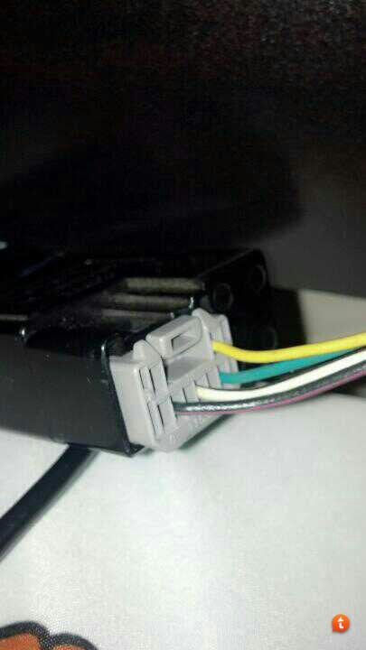
Clutch Cancel Switch Wiring

danthemanx07

New member
Anyone wired one of these up before? I am having a little trouble because my wire colors are not the same as in the FSM as I have pieced my switch and wiring together at different times.

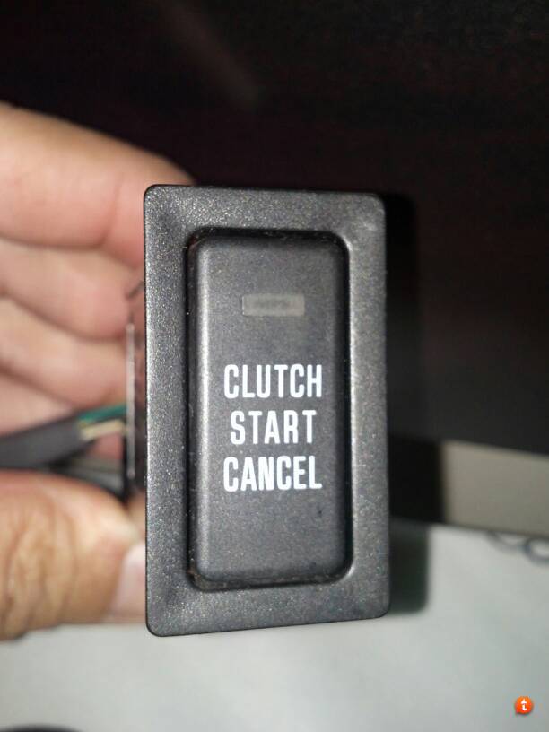
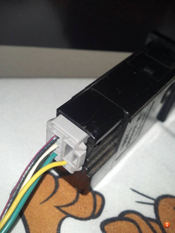
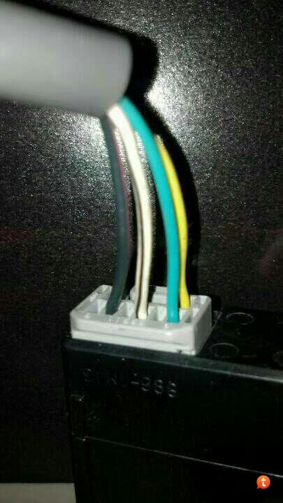
Anyway, I have a switch from a 1998 with three wires orientated in the picture below.
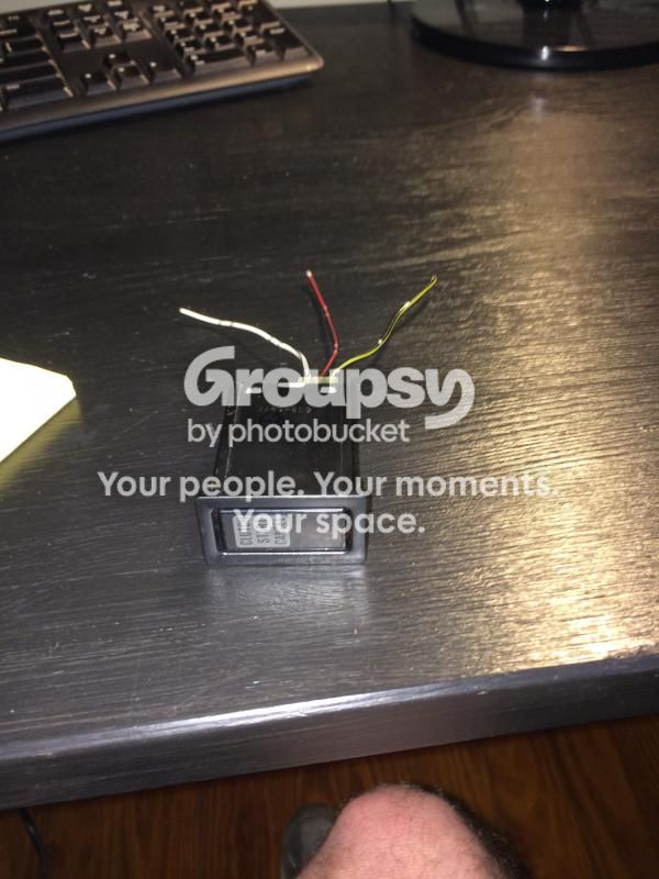


I gather that two of the wires must connect inline with the clutch cancel switch at the bottom of the clutch pedal.

I have two questions though -
(1) anyone know which two? I would guess the two black striped ones, but I'd rather not guess.

(2) where does the third one go? I can't quite make sense of the factory service manual wiring diagram.

It has taken me nearly 4 years to get around to this after swapping in my manual transmission - SO it is about d@mn time...

Thanks for the help.
 
Register to hide this ad
This is the wiring diagram I have. The cancel switch is circled. If I could figure out which wires are which by physical orientation this would be easy. But wires colors are no help right now unless someone wants to volunteer to pop their switch out real quick and see what order the wires are in...

 
This is the wiring diagram I have. The cancel switch is circled. If I could figure out which wires are which by physical orientation this would be easy. But wires colors are no help right now unless someone wants to volunteer to pop their switch out real quick and see what order the wires are in...

I don't have an EWD for a 98, so I can't find the connector diagram you need. And that IS what you need. The colors won't matter if you know which terminal is which. Look at the connector itself and see if you can find the terminal numbers. Most, if not all Toyota connectors have the terminal numbers on them.

Knowing that, you can follow the diagram like this. I may have the numbers wrong because I can't see your diagram very clearly even when I tried enlarging it.

Term 1(upper left in your diagram) comes from fused ignition power, you can follow it in the diagram to the upper left fuse.

Term 7(upper right in your diagram) from the "gauge" fuse.

Term 5(lower right in your diagram) goes to ground.

Term 3(lower left in your diagram) goes to the starter relay{this may also be the upstream side of your clutch switch}

Now the issue I see is that you only have 3 wires, but I think you could rectify that with another junkyard part, either compete or just enough to steel a pin and wire.

The switch acts as a relay for the relay, allowing the starter relay get power on the switching side even though the normal conditions have not been met(ie clutch depressed or p/n switch activated)

Should be simple, good luck!

:couch2:
 
I don't have an EWD for a 98, so I can't find the connector diagram you need. And that IS what you need. The colors won't matter if you know which terminal is which. Look at the connector itself and see if you can find the terminal numbers. Most, if not all Toyota connectors have the terminal numbers on them.

Knowing that, you can follow the diagram like this. I may have the numbers wrong because I can't see your diagram very clearly even when I tried enlarging it.

Term 1(upper left in your diagram) comes from fused ignition power, you can follow it in the diagram to the upper left fuse.

Term 7(upper right in your diagram) from the "gauge" fuse.

Term 5(lower right in your diagram) goes to ground.

Term 3(lower left in your diagram) goes to the starter relay{this may also be the upstream side of your clutch switch}

Now the issue I see is that you only have 3 wires, but I think you could rectify that with another junkyard part, either compete or just enough to steel a pin and wire.

The switch acts as a relay for the relay, allowing the starter relay get power on the switching side even though the normal conditions have not been met(ie clutch depressed or p/n switch activated)

Should be simple, good luck!

:couch2:

Hmm... Maybe I have the wrong wiring diagram - or the wrong switch...

I can't find any terminal numbers on this guy anywhere.


Yeah maybe that is a 1st gen switch. The numbers should be on the connector not the switch. But if that connector only has 3 terminals, its the wrong one. You could still make it work, a DVOM and some patience is all you need. I would recommend getting the correct one, makes it easier for you or a future owner to trouble shoot down the line. But if you want to use it, we can figure it out.

:couch2:
 
Yeah maybe that is a 1st gen switch. The numbers should be on the connector not the switch. But if that connector only has 3 terminals, its the wrong one. You could still make it work, a DVOM and some patience is all you need. I would recommend getting the correct one, makes it easier for you or a future owner to trouble shoot down the line. But if you want to use it, we can figure it out.

:couch2:

Gotcha. Yeah nothing on the connector either. I think I see my problem... This switch came out of a 1997 and not a 1998 - just went back and checked the part out thread on here. Wiring must have been slightly different. Guess I need to find a 1997 EWD or a 1998 switch. Thanks for the help. I'll post back up when I get hands on one of those.

Sh!t - yeah. Switches are different after 1997.


Last edited:
Yeah maybe that is a 1st gen switch. The numbers should be on the connector not the switch. But if that connector only has 3 terminals, its the wrong one. You could still make it work, a DVOM and some patience is all you need. I would recommend getting the correct one, makes it easier for you or a future owner to trouble shoot down the line. But if you want to use it, we can figure it out.

:couch2:

Alright got the right wiring diagram now I think.

Anyway to make this switch work given the differences in the wiring? My wiring is akin to the 1998 diagram.

 
Well, no guarantees. It appears there are four wires on the later switch. These are: 1)power, 2) ground, 3)clutch by-pass upstream of switch, and 4)clutch by-pass downstream of switch. There are three wires on the early switch, 1)power, 2)ground and clutch by-pass downstream of switch combined, and 3) clutch by-pass upstream of switch. You could bridge the ground and downstream by-pass and pray. Those two wires are bridged truckside on the 4-wire circuit, so bridging them at the relay should be no problem. I can match those up year to year. I doubt it will set the truck on fire, but this is really winging it. I'd welcome a second opinion [MENTION=102597]IBallEngineer[/MENTION] .

So, Function: color on switch >>>color on switch harness.

Power: Black/yellow (T3)>>>>>Black/yellow (T7)
Upstream of Switch: Black/red (T2)>>>>Solid Green* (T1)
Downstream: White/Black (T1)>>>>>Black/White*(T3*)(or just do nothing, the connection below is all you need)
Ground:White/Black (T1)>>>>White/Black (T5*)

*Items with an asterisk were best guess given resolution of the diagrams. Given context, I am 90% sure I have them right.

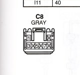
Finally, your 4-wire diagram is identical to my '99 paper EWD, so here is the pin-out to plug that is on your truck.
 

Attachments

  • C8 PIN-out.jpg
    C8 PIN-out.jpg
    69.9 KB · Views: 4,318
Last edited:
Well, no guarantees. It appears there are four wires on the later switch. These are: 1)power, 2) ground, 3)clutch by-pass upstream of switch, and 4)clutch by-pass downstream of switch. There are three wires on the early switch, 1)power, 2)ground and clutch by-pass downstream of switch combined, and 3) clutch by-pass upstream of switch. You could bridge the ground and downstream by-pass and pray. Those two wires are bridged truckside on the 4-wire circuit, so bridging them at the relay should be no problem. I can match those up year to year. I doubt it will set the truck on fire, but this is really winging it. I'd welcome a second opinion [MENTION=102597]IBallEngineer[/MENTION] .


Finally, your 4-wire diagram is identical to my '99 paper EWD, so here is the pin-out to plug that is on your truck.

What, no fires?! You take away ALL my fun!

Seriously though [MENTION=10169]TheDurk[/MENTION], you pretty much nailed it. Since he will be using the 3 wire connector and switch we can just forget about the downstream clutch switch connections. Here is how I see it in simple format using the colors on the switch in his pictures.

Black with Yellow to fused ignition circuit (gauge fuse preferably)

Black with red to the UPSTREAM side of the clutch switch.

White with Black to ground.

That's it!

:couch2:
 
What, no fires?! You take away ALL my fun!

Seriously though [MENTION=10169]TheDurk[/MENTION], you pretty much nailed it. Since he will be using the 3 wire connector and switch we can just forget about the downstream clutch switch connections. Here is how I see it in simple format using the colors on the switch in his pictures.

Black with Yellow to fused ignition circuit (gauge fuse preferably)

Black with red to the UPSTREAM side of the clutch switch.

White with Black to ground.

That's it!

:couch2:

Actually, it won't work at all. The three-wire circuit is set up to interrupt the ground side of the starter relay coil circuit. The four wire circuit is set up to interrupt on the power side of the coil. Because there is no way to separate the downstream side of the switch from ground, you end up grounding both sides of the Starter relay when you put the 3-wire switch on the 4-wire circuit. This will be a direct short when you turn the key and power is sent to the relay. DON"T DO THIS!! TheDurk is an idiot. I knew there was something wrong. Yeah, it could cause a fire.
[MENTION=102597]IBallEngineer[/MENTION] ???

OP: You need a 4-wire switch.84480-35030
 
Last edited:
Actually, it won't work at all. The three-wire circuit is set up to interrupt the power side of the starter relay coil circuit. The four wire circuit is set up to interrupt on the ground side of the coil. Because there is no way to separate the downstream side of the switch from ground, you end up grounding both sides of the Starter relay. This will be a direct short when you turn the key and power is sent to the relay. DON"T DO THIS!! TheDurk is an idiot. I knew there was something wrong.
[MENTION=102597]IBallEngineer[/MENTION] ???

OP: You need a 4-wire switch.

:doh: Begging your pardon sir [MENTION=10169]TheDurk[/MENTION]. I always wanted to say that.

The three wire switch is NOT set up to interrupt the power side of the coil circuit, at least not in the diagram the OP posted. It is set up to BYPASS the clutch switch. Despite my evil side showing a little, this set up will NOT burn his rig down.

It is the 4 wire version which supplies power to the starter relay coil circuit.

But that doesn't matter, as long as the OP follows the instructions in my previous post.

Man this is fun. I could do this all day!

:snacker:
 
:doh: Begging your pardon sir [MENTION=10169]TheDurk[/MENTION]. I always wanted to say that.

The three wire switch is NOT set up to interrupt the power side of the coil circuit, at least not in the diagram the OP posted. It is set up to BYPASS the clutch switch. Despite my evil side showing a little, this set up will NOT burn his rig down.

It is the 4 wire version which supplies power to the starter relay coil circuit.

But that doesn't matter, as long as the OP follows the instructions in my previous post.

Man this is fun. I could do this all day!

:snacker:

Yeah, but the pedal CLUTCH SWITCH itself is on the power side of the starter relay coil in the 4-wire circuit, which is what I was talking about. So the upstream leg of the cancel switch goes to the fuse. When the 3-wire switch closes, it will go straight to ground, even following your instructions. Not good.(I admit I had power and ground swapped in my last post.)

With the 3-wire switch you have three choices for the W-B wire:

1) Connect to ground>>>direct short.
2) Connect to downstream leg of clutch pedal switch>>>no ground to cancel switch circuitry, so switchee no workee.
3) Connect to both>>>see #1 above.

4-wire circuit needs 4-wire switch. No way around it.
 
Last edited:
Yeah, but the pedal CLUTCH SWITCH is on the power side of the starter relay coil in the 4-wire circuit, which is what I was talking about. So the upstream leg of the cancel switch goes to the fuse. When the 3-wire switch closes, it will go straight to ground, even following your instructions. Not good.(I admit I had power and ground swapped in my last post.)

Yes, that is true [MENTION=10169]TheDurk[/MENTION], although I haven't found a clutch switch on the later EWD. But since the P/N switch interrupts the power side(very un-Toyota), I'll assume the clutch switch does too. Easy enough to rectify though if we use an added relay or if we invert the connections on the switch, provided there are no internal diodes.

Let me throw something out just for fun. The OP stated in his first post that he swapped in the Manual transmission, shouldn't we test his clutch switch to see what it is switching?

Man, this is getting good!

:bluejump:
 
OK, should have looked at the diagram before I opened my mouth about inverting the connections. Diodes everywhere!

No problem, we can switch polarity with a relay!

:doh:
 
Yes, that is true [MENTION=10169]TheDurk[/MENTION], although I haven't found a clutch switch on the later EWD. But since the P/N switch interrupts the power side(very un-Toyota), I'll assume the clutch switch does too. Easy enough to rectify though if we use an added relay or if we invert the connections on the switch, provided there are no internal diodes.

[It has lots of diodes. But with an extra relay, yes I think there is a way.]

Let me throw something out just for fun. The OP stated in his first post that he swapped in the Manual transmission, shouldn't we test his clutch switch to see what it is switching?

[Good idea.]

Man, this is getting good!

[Agreed.]

:bluejump:

My answers in bold.
 
So [MENTION=84972]danthemanx07[/MENTION], can you test the clutch switch and see if you have 12V going through it, or if you have reduced voltage and ground? Check both sides of the switch with a voltmeter and check resistance to ground at both sides as well.

:popcorn:
 
Man - you guys probably spilled more 12v wiring knowledge in a few posts than I have ever had.
[MENTION=102597]IBallEngineer[/MENTION] - I will test as you have described tonight and let y'all know the results.
[MENTION=105773]busmup808[/MENTION] - that looks like the correct switch - but the wire colors are different - what did that one come out of?
 

Members online

Forum statistics

Threads
278,309
Messages
3,554,071
Members
248,016
Latest member
Advally Service

Trending content

Back
Top