matoolie
New member
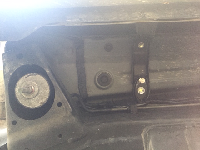
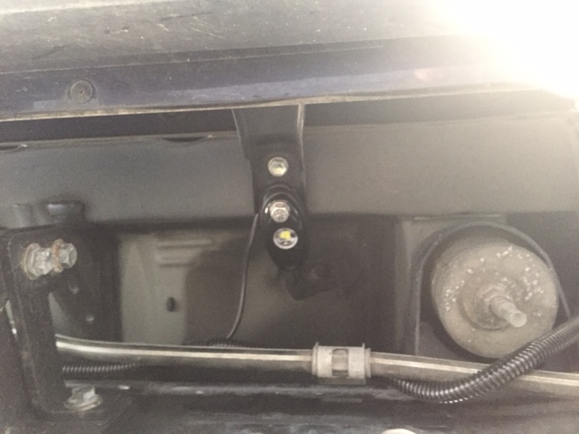
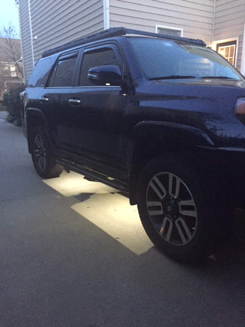
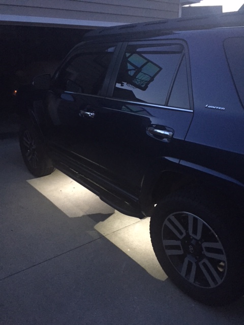
I’ve been wanting to add some LED “rock lights” under the truck that I could turn ON with a switch, but also turn ON when unlocking or approaching the vehicle. Which meant I wanted to have the new lights controlled by the puddle lights in the mirrors as the puddle lights illuminate with unlocking, and also when I simply walk up to the truck as I have the Smart Key system.
There are two main issues with using the puddle lights as the “control” for the new rock lights that have made me reluctant to pursue this:
1. First, the puddle lights have a “theater” effect where they ramp up and down in brightness. This means the voltage to the lights varies between 0 and 12V during ramp ON and OFF. This would cause a normal 12V relay to “buzz” and arc, resulting in short relay life and flickering of the LED’s. This could be addressed with a capacitor in the control/coil circuit of the relay, but then you have to protect the OEM puddle light circuit from the capacitor discharge with a diode. If the diode fails, then you would back feed current into the puddle light circuit…..see #2.
2. The puddle lights are controlled and driven directly by an output from the main body ECU, not through a normal relay type setup. As a result, there is a potential risk of damaging the ECU with additional load of a relay or if something goes wrong with diodes/capacitors as described in #1. This is what scared me the most and, thus protecting the ECU was the #1 priority.
I came up with a way to control the rock lights with the puddle light output from the ECU, while avoiding relay buzzing and providing some isolation to the ECU for peace of mind. See diagram below:
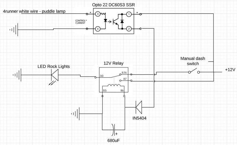
I used a solid state relay (SSR) to control a normal 12V mechanical relay. The purpose of the SSR is to isolate the puddle light circuit (4runner white wire) from the circuit for the rock lights, but allowing the circuit to control a 12V mechanical relay that turns the actual rock lights ON/OFF. The 12V mechanical relay is only needed as I also wanted to control the new LED lights with a separate switch on the dash for manual control anytime as stated above. If you want to control the rock lights with only the puddle lights, then this 12V mechanical relay could be eliminated and the rock lights can be powered directly by the output of the SSR, while still isolating the puddle light circuit.
You will notice I have a capacitor across the coil (terminals 85 and 86 of 12V relay). I originally did not have this, but the relay “buzzed” during turn ON and OFF of the rock lights. The capacitor resolved this, while the IN5404 diode prevents back feeding current when the capacitor is discharging.
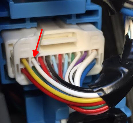
The white power wire for the puddle lights that I used is located in the drive side kick panel.
The input impedance of the SSR on the control side is 1000 ohms, so the additional amperage load on the puddle light circuit is minimal, especially when combined with the lower current draw of the LED’s I used to replace the original incandescent bulbs in the puddle lights themselves. And yes the rock lights do not ramp up and down in brightness with the puddle lights, but this doesn’t bother me a bit.
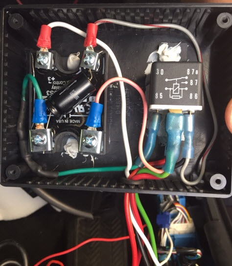
As the SSR has exposed screw terminals I used a “project box” to contain/protect it, as well as the standard 12V mechanical relay, and extended wires out of the box for connections. I was able to fit the box up in the dash behind the OEM switch panel area to the left of the steering wheel.
There are two main issues with using the puddle lights as the “control” for the new rock lights that have made me reluctant to pursue this:
1. First, the puddle lights have a “theater” effect where they ramp up and down in brightness. This means the voltage to the lights varies between 0 and 12V during ramp ON and OFF. This would cause a normal 12V relay to “buzz” and arc, resulting in short relay life and flickering of the LED’s. This could be addressed with a capacitor in the control/coil circuit of the relay, but then you have to protect the OEM puddle light circuit from the capacitor discharge with a diode. If the diode fails, then you would back feed current into the puddle light circuit…..see #2.
2. The puddle lights are controlled and driven directly by an output from the main body ECU, not through a normal relay type setup. As a result, there is a potential risk of damaging the ECU with additional load of a relay or if something goes wrong with diodes/capacitors as described in #1. This is what scared me the most and, thus protecting the ECU was the #1 priority.
I came up with a way to control the rock lights with the puddle light output from the ECU, while avoiding relay buzzing and providing some isolation to the ECU for peace of mind. See diagram below:
I used a solid state relay (SSR) to control a normal 12V mechanical relay. The purpose of the SSR is to isolate the puddle light circuit (4runner white wire) from the circuit for the rock lights, but allowing the circuit to control a 12V mechanical relay that turns the actual rock lights ON/OFF. The 12V mechanical relay is only needed as I also wanted to control the new LED lights with a separate switch on the dash for manual control anytime as stated above. If you want to control the rock lights with only the puddle lights, then this 12V mechanical relay could be eliminated and the rock lights can be powered directly by the output of the SSR, while still isolating the puddle light circuit.
You will notice I have a capacitor across the coil (terminals 85 and 86 of 12V relay). I originally did not have this, but the relay “buzzed” during turn ON and OFF of the rock lights. The capacitor resolved this, while the IN5404 diode prevents back feeding current when the capacitor is discharging.
The white power wire for the puddle lights that I used is located in the drive side kick panel.
The input impedance of the SSR on the control side is 1000 ohms, so the additional amperage load on the puddle light circuit is minimal, especially when combined with the lower current draw of the LED’s I used to replace the original incandescent bulbs in the puddle lights themselves. And yes the rock lights do not ramp up and down in brightness with the puddle lights, but this doesn’t bother me a bit.
As the SSR has exposed screw terminals I used a “project box” to contain/protect it, as well as the standard 12V mechanical relay, and extended wires out of the box for connections. I was able to fit the box up in the dash behind the OEM switch panel area to the left of the steering wheel.
Last edited: