CORRECTED DESCRIPTION - 96 Turn Signal Issue

Deleted my earlier post and adding better problem description. On my 96, the front right turn signal will not work, even with bulb replacement, and the right rear works but flashes very fast. Left side turns work fine and there have been no mods (e.g, led, etc).

Anyone have a suggestion?

Thanks
 
Register to hide this ad
I just took a look at the wiring diagram, and everything is common between the front and rear except the wiring. There's no separate front and rear relays or flashers, or anything like that. You're looking at a broken wire, or connection, or maybe a bad socket. I'd start by putting a meter to the socket and see if you're getting voltage, and then check the continuity of the ground wire to the chassis. The ground wires are white with a black tracer. The LH signal wires are Yellow w/Green, and the RH are Green w/Yellow.

The fast blinking is normal when a bulb isn't working, so don't get hung up on that. It's normal under these circumstances. Just out of curiosity, what happens when you turn your hazards on?
 
Just out of curiosity, what happens when you turn your hazards on?

With hazards,I get normal blinking on lf, lr and rr, but nothing on fr. Also, at the same time this reared it's ugly head, the ABS light came on and stayed on....can't be related, can it...maybe the turn signal and ABS sensor wires in the same harness somewhere and shorted together?
 
With hazards,I get normal blinking on lf, lr and rr, but nothing on fr. Also, at the same time this reared it's ugly head, the ABS light came on and stayed on....can't be related, can it...maybe the turn signal and ABS sensor wires in the same harness somewhere and shorted together?

It might not be related, but I wouldn't completely rule out a harness issue that's causing both.

Did you run over anything that could have damaged the wiring on that side? It's also possible that the turn signal and ABS sensor share a ground point, and that's the problem.

The wiring all comes together at a block on the diagram, but I can't tell exactly where it's at.

Here's a link to all the wiring just in case you don't have it already:
1996 to 2002 Toyota 4Runner OEM Repair and Wiring Manuals
 
It might not be related, but I wouldn't completely rule out a harness issue that's causing both.

It's also possible that the turn signal and ABS sensor share a ground point, and that's the problem.

I would look into this first. Ill bet it a bad ground wire causing both these issues.
 
It might not be related, but I wouldn't completely rule out a harness issue that's causing both.

Did you run over anything that could have damaged the wiring on that side? It's also possible that the turn signal and ABS sensor share a ground point, and that's the problem.

The wiring all comes together at a block on the diagram, but I can't tell exactly where it's at.

Here's a link to all the wiring just in case you don't have it already:
1996 to 2002 Toyota 4Runner OEM Repair and Wiring Manuals

Thanks, I'll try to check out ground points and connections. Everything was working until a friend did a timing belt/water pump change and also replaced intake gaskets and valve cover gaskets. It's possible in removing the manifold something got displaced, because the problems were immediately afterward when the Runner was started.

The link to the wiring worked fine; the link to the repair manual similarly opened a table of contents, but all of the links I tried gave me the old "The page cannot be found" error message. Is there a more current link because it looks like it contains invaluable information?
 
Thanks, I'll try to check out ground points and connections. Everything was working until a friend did a timing belt/water pump change and also replaced intake gaskets and valve cover gaskets. It's possible in removing the manifold something got displaced, because the problems were immediately afterward when the Runner was started.

The link to the wiring worked fine; the link to the repair manual similarly opened a table of contents, but all of the links I tried gave me the old "The page cannot be found" error message. Is there a more current link because it looks like it contains invaluable information?

http://tacoma.site40.net/4Runner_96-02_Repair&Wiring/local%20files/repair.html

This link works.

The grounds for BOTH front signal lamps are joined at the J1 connector in or around the main engine room fuse block. Easier to just check the harness at the bulb and see if there is a good ground present.

:couch2:
 
Problem Update-96 Right Turn Front Not working

Well, turns out the ground is good, but there is no voltage on the other line. Checked the other (left) side to see what healthy looks like and found voltage. Right rear works fine, other than the rapid flashing because of the open on the front circuit. On hazards, left front and rear and right rear all blink at normal rate, but no action from front right.

My understanding is that everything for the right side turn signals is common through the switch and relay, then somewhere it splits to hit front and rear. Any idea where this point is so I can check for continuity from that point on to the front light and maybe find what would seem to be an open wire?

Any help appreciated. Only have 3 days left to get this fixed for state inspection, and I don't want to have to refer it to stealership for pricey fix unless absolutely necessary.

Thanks

 
Well, turns out the ground is good, but there is no voltage on the other line. Checked the other (left) side to see what healthy looks like and found voltage. Right rear works fine, other than the rapid flashing because of the open on the front circuit. On hazards, left front and rear and right rear all blink at normal rate, but no action from front right.

My understanding is that everything for the right side turn signals is common through the switch and relay, then somewhere it splits to hit front and rear. Any idea where this point is so I can check for continuity from that point on to the front light and maybe find what would seem to be an open wire?

Any help appreciated. Only have 3 days left to get this fixed for state inspection, and I don't want to have to refer it to stealership for pricey fix unless absolutely necessary.

Thanks

OK, not exactly, they don't share anything after the Body ECU. You need to check the connector E1 terminal 7, at least on the 02 wiring diagram. Double check the color of the wire at the bulb, and make sure it matches.
 
OK, not exactly, they don't share anything after the Body ECU. You need to check the connector E1 terminal 7, at least on the 02 wiring diagram. Double check the color of the wire at the bulb, and make sure it matches.

Thanks. Can you point me to the E1 location?

I would hope the colors would match, because this lamp was working two weeks ago before the intake was pulled off for gasket replacement, but I don't think it's anything that didn't get reconnected because all of the other lights at right front work and I'm pretty certain they would be in the same harness.

Frustrating, to say the least.

Appreciate the feedback, IBallEngineer
 
Thanks. Can you point me to the E1 location?

I would hope the colors would match, because this lamp was working two weeks ago before the intake was pulled off for gasket replacement, but I don't think it's anything that didn't get reconnected because all of the other lights at right front work and I'm pretty certain they would be in the same harness.

Frustrating, to say the least.

Appreciate the feedback, IBallEngineer

Sorry, I meant 1E connector on the body ECU. In this diagram you can see it's location on the ECU, but it is for a 2002. So yours may be different.

http://tacoma.site40.net/4Runner_96-02_Repair&Wiring/techinfo.toyota.com/ileaf/ewdtmc2/ewdtmpdf/ewdsourc/2002/024runne/relayloc/relayloc.pdf

If you have power coming out of that connector at T7, than you have an open circuit between there and the lamp. If you don't, than it is likely the Body ECU.

:snacker:
 
Sorry, I meant 1E connector on the body ECU. In this diagram you can see it's location on the ECU, but it is for a 2002. So yours may be different.

http://tacoma.site40.net/4Runner_96-02_Repair&Wiring/techinfo.toyota.com/ileaf/ewdtmc2/ewdtmpdf/ewdsourc/2002/024runne/relayloc/relayloc.pdf

If you have power coming out of that connector at T7, than you have an open circuit between there and the lamp. If you don't, than it is likely the Body ECU.

:snacker:

Going to check this tonight, but can you tell me if it is a straight run from the T7 point at the ECU to the light or is there a junction point under the hood where I could also check for power and perhaps isolate the section of wire that is open? Presuming the open is downstream of an underhood junction, I could then run a parallel line to bypass the break and get my vehicle inspected. I'm hoping to not have to run a wire all the way through the firewall to get to the ECU junction if the T7 is hot.

Thanks
 
If you have power coming out of that connector at T7, than you have an open circuit between there and the lamp. If you don't, than it is likely the Body ECU.

:snacker:

I'd be really surprised if it's the ECU, because those connections should just be junctions inside. I can't think of any reason they'd ever need to separate the front and rear turn signal indications by any kind of logic in the ECU. Even the "fast flash" function is done externally by the flash relay. There must be some good reason for passing the signals through that connector though. :noidea:
 
Going to check this tonight, but can you tell me if it is a straight run from the T7 point at the ECU to the light or is there a junction point under the hood where I could also check for power and perhaps isolate the section of wire that is open? Presuming the open is downstream of an underhood junction, I could then run a parallel line to bypass the break and get my vehicle inspected. I'm hoping to not have to run a wire all the way through the firewall to get to the ECU junction if the T7 is hot.

Thanks

No connector at least in the 02 wiring diagram. Straight run.
 
I'd be really surprised if it's the ECU, because those connections should just be junctions inside. I can't think of any reason they'd ever need to separate the front and rear turn signal indications by any kind of logic in the ECU. Even the "fast flash" function is done externally by the flash relay. There must be some good reason for passing the signals through that connector though. :noidea:

Can anyone tell me the wiring sequence? Does trhe signal come from the stalk through the ECU to the flasher relay? Does the signal split at the relay to left and right and then split next front and rear, or is there a separate pin for each corner of the truck (LF,RF,RF,RR), or just where does a split occur, because the lefts are fine and the right rear does the fast flash, but right fronmt is dead.

Thanks
 
Going to check this tonight, but can you tell me if it is a straight run from the T7 point at the ECU to the light or is there a junction point under the hood where I could also check for power and perhaps isolate the section of wire that is open? Presuming the open is downstream of an underhood junction, I could then run a parallel line to bypass the break and get my vehicle inspected. I'm hoping to not have to run a wire all the way through the firewall to get to the ECU junction if the T7 is hot.

Thanks

No junctions on the diagram.

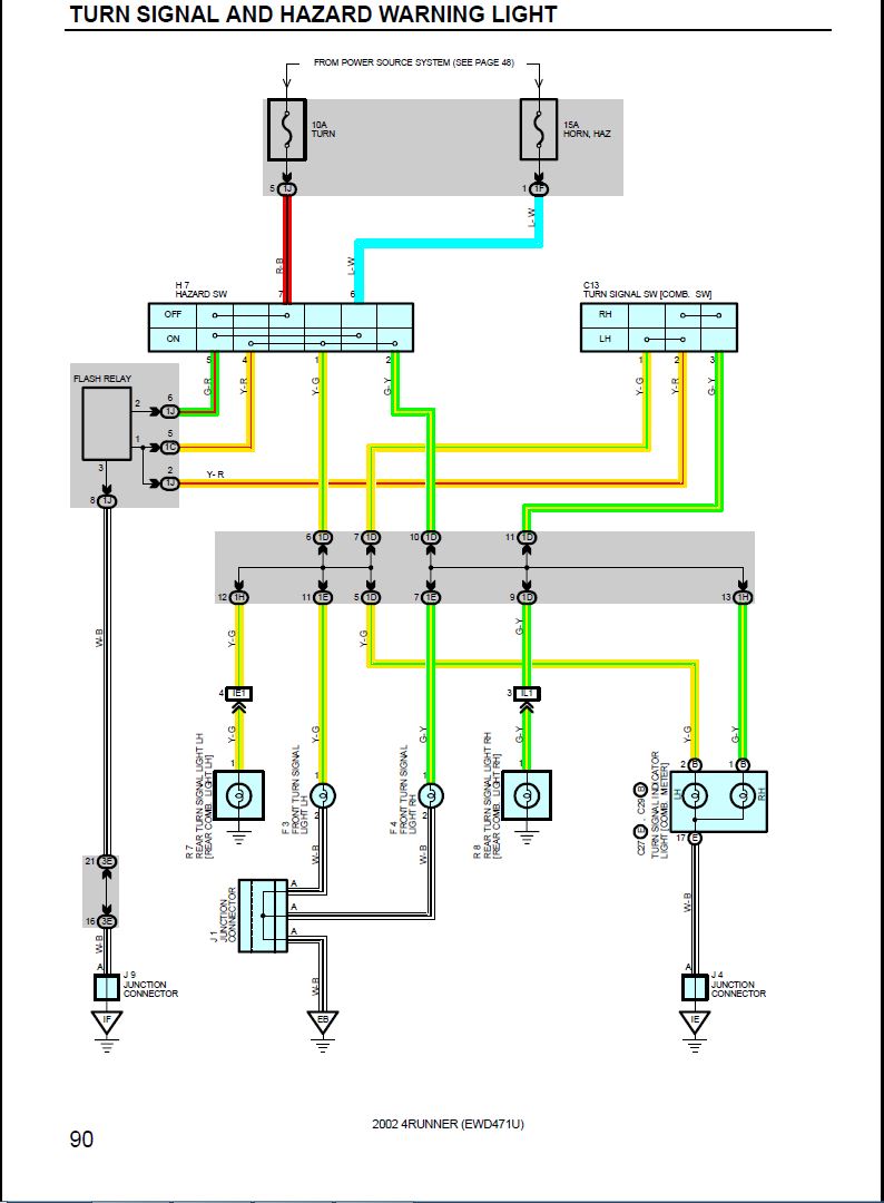
16597458408_de4cbe9120_o.jpg
 
Can anyone tell me the wiring sequence? Does trhe signal come from the stalk through the ECU to the flasher relay? Does the signal split at the relay to left and right and then split next front and rear, or is there a separate pin for each corner of the truck (LF,RF,RF,RR), or just where does a split occur, because the lefts are fine and the right rear does the fast flash, but right fronmt is dead.

Thanks

I posted the diagram above. There's a separate pin coming out of the Body ECU for each corner, but it looks like they're just using it as a junction point. The flash relay is common for both left and right, as well as hazards. All the wiring between the flasher and the ECU has to be ok, otherwise you'd have both lights on one side not working, so you can rule that out.

From what I can tell all that's really left is the wire between the socket and the ECU, the connector at the ECU, and the board itself. I'm still a little puzzled as to why they go through the ECU board at all. It may be that was just an easy way to make the junction for all five wires and it's just simple circuit board traces between the pins, or there may be something more to it, possibly isolation diodes. I'm betting on the wiring or the connector personally.
 

Members online

Forum statistics

Threads
278,310
Messages
3,554,079
Members
248,016
Latest member
Advally Service

Trending content

Back
Top