CSix Build Thread

CSix

New member
CSix Build –

Welcome to my 2015 T4R Trail Build and Tracking Thread!


Mod threads:
Trail Badges
Cooper Busmann Power Distribution Box
ARB Air Compressor
Air Manifold
Under Hood Light
Rear facing lights
Presta or Shrader Air Inflator
Bilstein 6112/5160 Suspension
Thule AeroBlade rack and Paceline bike Carriers


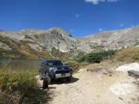
I’ll be using this thread to track my mods, upgrades and travels. My Trail build will be a bit civilized compared to past vehicles and I highly doubt I’ll be taking it up Pritchett Canyon any time soon. But, I will be all over Colorado high country.

There are some great write-ups in this forum. Thanks for the inspiration!

Current Stats:
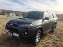
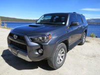
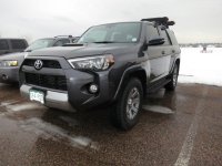
2015 T4R Trail Premium, Navigation etc
Bilstein 6112/5160 Suspension combo set to #3 at 2" front and Icon 2" springs in rear
Tires - Nitto Terra Grappler G2’s in stock 265/75-17
Blizzak DMV1 for winter in stock 265/75-17
Thule AeroBlade Rack with Paceline Bike Carriers
3M Window tint matching
3M Clear Bra on front, hood and mirrors
Factory Trail running boards
Custom “Trail” Badging
3.5’ by 6’ rubber cargo mat – A must with bikes inside (Thanks TRDPRORUNNER)
Weathertech floor liners – Love them but they do get slippery
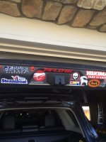
Rear lift gate closet decals – love the stealth way to hide decals
Cooper Busmann power distribution box – 5-fused 35amp relays and 5 fused 15amp power sources
Aironboard switches – They fit!
Custom wiring loom (made by me) for 5 switches
ARB Air Compressor CKMA12
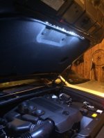
Under Hood LED light strip with switch
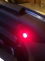
Rigid SR-Q lights rear facing

Planned:
VisionX Light Cannons 6.7” along with 4.5’s
Rechargeable light Mod – noodling a way to mount a robust rechargeable light
Air NPT fitting to the back of the truck (air up and to fill up bike tires)
Front ARB locker
ARB Awning
 

Attachments

  • fixed.jpg
    fixed.jpg
    46.5 KB · Views: 4,659
Last edited:
Register to hide this ad
CSix Pics...

A few Pics...

Loch Lomond... Colorado
LLomond.jpg

Loch Lomond Fishing
llomond2.jpg

Turquoise Lake, Colorado
Tlake1.jpg

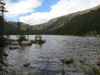
Timberline Lake outside of Leadville, CO
Tmbrlake1.jpg

Ice Fishing in Chatfield Lake – Pure ice on the ground and 5 deg
cfield1.jpg

Lake Trout – The wife fishes. This lake trout was caught in Lake Granby.
ltrout1.jpg
 

Attachments

  • LLomond.jpg
    LLomond.jpg
    63.7 KB · Views: 5,251
  • llomond2.jpg
    llomond2.jpg
    54.3 KB · Views: 4,775
  • Tlake1.jpg
    Tlake1.jpg
    60.8 KB · Views: 4,705
  • Tmbrlake1.jpg
    Tmbrlake1.jpg
    87.5 KB · Views: 4,797
  • Tmbrlake2.jpg
    Tmbrlake2.jpg
    102.2 KB · Views: 4,770
  • cfield1.jpg
    cfield1.jpg
    74.3 KB · Views: 4,741
  • ltrout1.jpg
    ltrout1.jpg
    69.6 KB · Views: 4,728
Last edited:
Mod 0.5: Custom Trail Badges

Mods

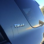
Mod 0.5: Custom Trail Badges – I had these made by that California Toyota dealer while she was in the shop. See posts in the General Discussions… I just recently put them on around the custom TRAIL badges were being made. I’ve always de-badged but, I kinda like this… I get compliments… really…
 

Attachments

  • trailbdge.jpg
    trailbdge.jpg
    36.1 KB · Views: 4,694
Mod #1 Cooper Bussman power distribution box with 5 fused 35amp relays and 5 fused n

Mod #1 Cooper Bussman power distribution box with 5 fused 35amp relays and 5 fused non-relay
Universal Relay Fuse Auxiliary Distribution BOX Block Jeep Cooper Bussmann | eBay

Disclaimer – This is what I did to the best of my memory to fabricate and mount a wiring harness and power distribution box. No warranties will be given or implied. Actual results may vary. I have seen several rather good write ups on installing a Power Distribution Box so I thought I’d add my own distinctiveness to the collective… Also, there is a lot of work involved. Enjoy…

A power distribution system is really just an additional fuse and relay box used to power your auxiliary devices. Reasons to have one: additional centralized power not patched into existing fuses boxes; organization of relays so you don’t have them and their wires all over the engine bay, and once it’s set up you can add auxiliary devices fairly easy.

This power distribution box has 5 fused 35 amp relays and 5 15 amp fused power sources for a total of 10 separate power sources. Wiring looms that come from the accessory may be cannibalized or may not even be necessary. In the end, the power box built will be connected with switches so when I add an accessory, I mount it and run the wire to the accessory line, ground, add a fuse to the power box where needed and the switch/accessory works.

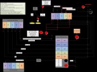
The first step is to lay out a design of what you want to do. In my case, I am building the power distribution box to handle an air compressor, rear lights, spot lights, driving lights and an open relay for future use (Front Locker). I will also be using some of the 5 always on fused locations. Here is a Visio of my plan.

Visio diagram plan
visiot4.jpg

Next step is to get what you need to put together:
Switches from Air On Board
Wire – 16g for power box to switches with selected colors to match the wires from the power block
Bullet connectors in 16-22 (you can never have too many)
Butt splices 12-14
Crimping tool! Yes, save yourself the hassle right now and just get one
Heat shrink tubing and mini torch
Soldering iron, electrical solder
Electrical tape, black and white (to write on)
Zip ties, lots of them in several sizes. Small sizes help build the wiring loom
Diodes – 1n504 3amp for Headlight and aux power sources (may already be in a wiring loom)
T-Taps or Scotch wire connectors
Split wire covering for wires the engine bay
High Temp black paint
Bussmann BP/HHH ATM Add-A-Fuse

Then, plan where you want to mount the new Relay box while laying out what you want in a wiring harness. This will determine the wire lengths, ground locations, etc. I chose a location next to the other fuse boxes because they are close to the battery. The location selected uses existing bolt holes on the driver’s side.

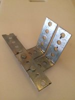
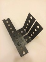
Fabricate a mounting Bracket: This took a bit of time trying to pick the right spot and fabricate the bracket. I used 1.5” support metal purchased at Home Depot cut, cleaned up, bolted and painted. I used existing M8 1.25 thread holes on the driver’s side engine compartment to mount fabricated L brackets with another strip bolted together and mounted close to the battery. I also used another piece of metal bolted to the underside of the bracket bolted to an existing M8 hole on the fender, for extra support.

Power Box Mounting Bracket, sanded – Before paint
pbracket1.jpg

Power Box Mounting Bracket, sanded – After paint:
pbracket2.jpg

Painted and attached
pbracket3.jpg


Build the loom to match your switches and power requirements per your diagram. Mine looks like the Medusa’s spawn with wires for 5 switches. All switches from AOB have four wires: Power from relay, Power from a 12v source where the power can be power from a switched 12V (for accessories like a compressor) or 12v source (from headlight high beams) depending on the switches use, power for dash lights and Ground. I have a diode on the power from the aux switched and headlight sources to protect the switch and prevent power flowing back. Watch the way you mount these. The Gray bar on the diode is on the switch side.

Measure the lengths of wire needed from the switch locations to the fire wall then to the switch block. Measure and measure again then give yourself another six inches.

I built the wiring loom so I could have all the connections to the switches inside the cab and run just one end to the power distribution box through the fire wall. I did this to route the wire loom through the firewall easier. I also labeled all the wires by the number on the fuse block and the intended use. I used white electrical tape and a sharpie. The wire color purchased also matched the wire color of the wires from the switch block. Color coordinated and fashionable!

Once the wire harness was completed, I also used a multi meter on an ohm setting to test to make sure all wires are routed correctly. I then wrapped the loom in black electrical tape and taped a folded piece of spare wire through to a point and the end of the loom. This end will actually contains a wire for each switch that connects to the relay, the ground and the power wire for the headlight activation. I’ll use the length of wire taped at the end to drag the wire loom through the firewall. Note: the thin spare folded and taped wire’s sole purpose is to pull the wire harness through the firewall grommet.

Compressor, Power Distribution Box, wire loom and assorted stuff… The wire harness has all black ground wires soldered together and only 1 ground passing to the fire wall. There are 5 switch accessory wires and a wire that powers the switch with 12v from high beams for the driving and spot lights…
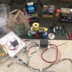
harness1.jpg


After building the internal loom, connect all bullet connectors to all the wire ends of the loom as well as the matching pair on the four wires to each switch. Do not put connectors on the side needing to pass through the firewall. (doh) This will be done later.

The 2015 4Runner Trail Premium has a spot in the firewall grommet that you can pass the wire loom through. It is a round nipple that can be snipped off leaving a rubber tunnel big enough for 8 16g wires to pass through. I pushed a coat hanger through first then the wire I taped to the wiring loom end and passed the wire passed right through. I then pulled that end of the wire through the firewall. My measurements were correct and the wires met at the relay box with enough to spare.

If you did it right, the color wires of the loom match the color of the wires to the switches on the relay box. I then added the bullet connectors and connected the switch wires to same color wires of the relay box. Add bullet connectors or butt splices to both ends, cover the wires with a wire covering for the engine compartment and zip tie it accordingly.

This note is in the compressor install… I only have the compressor installed right now so, I measured the accessory wire to the compressor, the pressure sensor wires, strung them from the mounting location to the relay box, wrapped in split loom wire cover, taped where appropriate and zip tied along the rear of the fire wall. Note: a pressure sensor is connected in-line to the compressor switch wire to turn it on and off at a range of 70-100 psi. This can be changed later too.

So double check connectors on the relay block will fit into the connectors on the wiring harness in the engine bay, check the connectors on the wiring harness that will connect to the switches from AOB. Then, check the connectors on the switches. Now’s the time to see if they are crimped well enough, trust me on this.

Since I labeled all the wires that match the switches and already added bullet connectors, the next step is rather easy. Connect them all up. The switch blanks in the dash are accessible by pulling down on the lower dash panel, next to the steering wheel. It pops out with a good pull. (Thanks Antman) The blanks have a spot in the top and bottom that can be pressed and they really just pop out. The blank next to the dimmer switch is a bit more challenging but a very small screw driver stuck in the bottom of the switch blank from the back pushes the mount clip and that too pops right out.

I have two aux devices that I want to run anytime; I used a Bussmann BP/HHH ATM Add-A-Fuse
that really just plugs into an open slot of the inside fuse box in the white box on the driver side box just under the left side of the dash, or replaces one of the fuses. Then, I connected bullet connectors to each side of the wire and plugged it in. I have this on un-switched power right now but will find a switched power fuse slot.

Pop out the old blanks, place the switch, with the connectors attached, through the hole… do not fully clip back in yet. Check wire length and see if your measurements worked. A second set of hands is really helpful in holding open the box, keeping a light on the work space and feeding you bites of slow roasted turkey sandwich and coffee.

Connect up the power… Measure the red and black wires from the power box to the battery. The red power wire is 8 gauge and the black ground is 10. Cut as needed and add a circle connector with a crimping tool. I Connected the power box ground, and the ground from the wire loom to the battery ground point on the side of the engine compartment next to the battery. Then I connected the heavy 8g wire to the battery. (no sparks… a good sign!)

Right now in my build, there are 3 fused relays and 5 fused power sources not used, but they will be. I pulled out the fuses then wrapped the aux wires in tape and split cover. When needed, I’ll pull out the appropriate “accessory” wire, add a fuse, connect the wire to the accessory and watch it work.

At this point I tested the switches and that I had power coming out of the accessory wire on the relay, with the multi meter. Everything works. Then I plugged everything back in, popped in the switches and buttoned all up.

What’s left? In my wiring harness, I have the blue wires connected as dimmer power so I just need to connect that wire to a wire coming from an existing dash illumination wire. I have read that wire is a green on any switch. I still need to connect the blue wire with a scotch or red T-Tap for the dash illumination. But, it’s tested with un-switched power. Next week, I will to tap into the high beams, for the driving lights but I decided to take Saker’s advice and use a 9005 extension that I’ll tap into. (just ordered from Amazon.

Dash opened up showing the backs of two AOB switches (green)
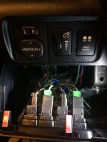
switches1.jpg

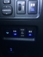
Switches installed - AOB switches fit pretty dang good.
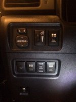
switches2.jpg

switches3.jpg

Note my switch locations. The Air compressor is a long way away and I will not accidently press it. The others, well, I just filled in the empty blank holes. The stock switches are keyed and only fit in one location. I can grind off the keying and mount them anywhere I want but that will be saved for a later date.

Almost done....

 

Attachments

  • visiot4.jpg
    visiot4.jpg
    73.7 KB · Views: 4,976
  • pbracket1.jpg
    pbracket1.jpg
    31.1 KB · Views: 4,789
  • pbracket2.jpg
    pbracket2.jpg
    25.2 KB · Views: 4,784
  • pbracket3.jpg
    pbracket3.jpg
    43.5 KB · Views: 4,759
  • harness1.jpg
    harness1.jpg
    72.6 KB · Views: 4,914
  • switches2.jpg
    switches2.jpg
    51.6 KB · Views: 4,982
  • switches1.jpg
    switches1.jpg
    47 KB · Views: 4,836
  • switches3.jpg
    switches3.jpg
    60.3 KB · Views: 4,765
Mod #1 Cooper Bussman power distribution box - Continued

There it is… Power box installed connected to switches and accessory wires ready to accessorize…
 

Attachments

  • pbox_cmpl.jpg
    pbox_cmpl.jpg
    38.3 KB · Views: 4,631
Mod #2 ARB Onboard Air Compressor

Mod #2 ARB Onboard Air Compressor Amazon.com: ARB CKMA12 Air Compressor: Automotive

The ARB Compressor CKMA12 is a small enough unit to mount that can deliver reasonable air pressure to stock sized tires. This compressor will be primarily used for airing up tires, inflating air mattresses, airing off trail dust and air hosing my dog and filling bicycle tires for me and my friends…

Since I have the Fused Relay block installed, the switch is already ready and waiting. I will mount the compressor and run the wires to the fuse block and be done.

The first step is to decide on the mounting location. I chose the passenger side of the engine bay because the location has three M6 holes screaming mount me; it’s in an open location and in the same loc as the one I had on my Jeep.

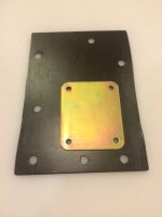
I figured a slab of steel plate with mount holes I drilled (use paper to trace the hole locations) that match the upper holes on the side of the engine compartment would be strong mount and keep the unit out of the way. I also have a connecting bracket mounted to the top of the wheel well for extra support. I did drill a hole in the fender for the support, and then painted after mounting to keep it water proof.

Ingredients:
ARB CKMA12 Air Compressor
Steel plate I had laying around but you can get from a hardware store
M6 grade 8 bolts for the side of the engine bay. About an 1.5 inches long.
Large Fender Washers – I use these for extra support
Large thin rubber Fender Washers to protect underneath mount
Spring lock washers
Black High Temp spray paint
M8 20 bolt (for the fender well)
Support metal 1.5” bolted to bottom of bracket to fender well

Fabrication of the mounting plate
arbcomp1.jpg

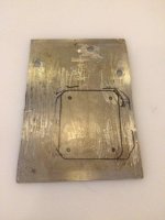
Mounting Plate and ARB Bracket. The three holes on the top match the three M6 holes in the side of the engine bay. The three on the bottom were drilled because I’d definitely use one, just did not know where I wanted the bottom support to go at the time. The gold plate is the stiffening plat that came with the ARB Compressor. Yes, the compressor needs all four of those holes.
arbcomp2.jpg

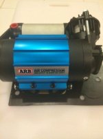
Test fit. I ended up rotating the actual mount 90 degrees.
arbcomp3.jpg

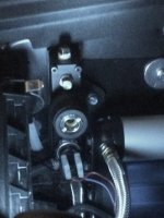
Once mounted, I cannibalized the ARB power and ground wires, because they have a connector that fits the ARB. I used the red wire that came with the ARB to connect to the accessory wire of my power block. I used the Black ground wire from the original ARB harness too. From the Power Box install, I measured the accessory power wire to the compressor, the pressure sensor wires, strung them from the mounting location to the relay box, wrapped in split loom wire cover, taped where appropriate and zip tied along the rear of the fire wall. Then, I connected the ground at the compressor location on an official ground site (one next to the air filter box). Note, a pressure sensor is connected in line to the compressor switch to turn it on and off at a range of 70-100 psi. This can be changed later too if I add an air tank. I added an air manifold and have a stainless ¼ NPT from the compressor to the manifold with the pressure sensor and an NPT quick disconnect. I also had a pressure relief valve… but, it leaked… so, I blocked up the empty locations on the manifold for later. One of the empty locations will route air back to the rear of the rig. I’ll be doing that later.

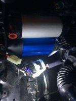
Compressor mounted on passenger side before being connected and powered
arbcomp4.jpg

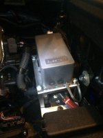
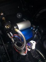
Compressor mounted and powered. Stainless Air hose connected to a Vivair Manifold. Pressure sensor and ARB NPT connector are on the manifold.
arbcomp5.jpg
 

Attachments

  • arbcomp1.jpg
    arbcomp1.jpg
    33.7 KB · Views: 4,720
  • arbcomp2.jpg
    arbcomp2.jpg
    25.2 KB · Views: 4,729
  • arbcomp3.jpg
    arbcomp3.jpg
    28.5 KB · Views: 4,716
  • arbcomp4.jpg
    arbcomp4.jpg
    34.9 KB · Views: 4,748
  • arbcomp5.jpg
    arbcomp5.jpg
    40 KB · Views: 4,750
Mod #2.5 Onboard Air Manifold

Mod #2.5 Onboard Air Manifold
So, on my 1985 CJ7, I had a full onboard air system, air 3 gal air tank, pressure sensor, NPT quick connect fittings fore and aft, pressure gauge in the cab and next to the compressor, fittings for lockers and an emergency relief valve. This was all built into a custom made manifold. That was probably one of the most complex puzzles I have done… made out of brass fittings and connectors and Teflon tape. I wish I had a pic. Well, now, I have learned a few things. This time… go buy one. They are not expensive. They keep the onboard air set up clean.

I saw this one on Amazon while looking for something else. Summit Racing has them for $15.
manifold1.jpg

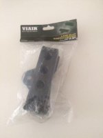
The air manifold is connected by a stainless ¼ NPT air hose from the compressor to the manifold. The manifold is mounted on one of the three bolts in the side of the engine bay holding up the compressor. The manifold is also mounted with a real thick washer under it to keep the Vivair mounting bracket nuts from scraping into the engine bay. Only one bolt is needed to mount the mounting bracket.

The current configuration has the ARB pressure sensor and an NPT quick disconnect in two locations. I also had a pressure relief valve… but, it leaked… so, I blocked up the empty locations on the manifold for later. One of the empty locations will route air back to the rear of the rig. I’ll be doing that later. Another location will be for a front air locker and another for a pressure gauge.

Manifold mounted next and connected to the ARB Air Compressor with a stainless ¼ NPT braided line, ARB NPT Quick connect and pressure sensor are mounted into the manifold.
manifold2.jpg
 

Attachments

  • manifold1.jpg
    manifold1.jpg
    23.1 KB · Views: 4,624
  • manifold2.jpg
    manifold2.jpg
    42.7 KB · Views: 4,657
Looking good, very nice work, I want to see it sometime. I live next to chatfield, although titanium is my material of choice, let me know when you are down again.
 
Titanium is my other favorite too.

I'll probably be riding up High Grade Sunday morning to around Noon. PM me when you are available.
 
Stealth Decal Placement

I've seen this on lift gates lately. Decals hiding stealthily under the lift gate only to be seen when the lift gate is open... adding a splash of color...
IMG_0272.jpg
 

Attachments

  • IMG_0272.jpg
    IMG_0272.jpg
    102.6 KB · Views: 4,666
Mod#3 Underhood lights

I just finished the latest mod after researching many real good under hood light mod ideas. I went with a street glow light strip and a lighted switch I already had. The light strip was purchased from Amazon. I do like the quality of the light strip and light it throws out but the wire connections are real thin.

http://www.amazon.com/StreetGlow-HD24WH-White-Heavy-Strip/dp/B00GZL97I4/ref=pd_ybh_24

The light strip is connected on the underside of the hood by a real good sticky tape and held in place by two self tapping sheet metal screws, at each end. The wire is run under the hood under layer coming out to the unswitched wire on the power distribution box. Then, connected to a lighted switch. I placed the switch on drivers side next to the battery. The wires are all contained in a split loom cover hidden under the plastic shroud on the side of the engine bay.

Streetglow light strip
IMG_0277.JPG

Lighted switch.
IMG_0278.JPG
 

Attachments

  • IMG_0277.JPG
    IMG_0277.JPG
    99.5 KB · Views: 4,376
  • IMG_0278.JPG
    IMG_0278.JPG
    86.7 KB · Views: 4,339
Dash Illumination for Switches

I just connected up the dash illumination for my switches . I originally set up a wire in the wiring harness for dash illumination but had not yet connected it. Many other posts noted the use of the green wire on any stock switch. So, I tapped into the green wire of the defroster switch. This wire does give power to the illumination but does not vary the brightness as the dash rheostat is changed. I did not test the other switches wires.

I also found a switched (accessory on) empty fuse location in the fuse box under the dash on the driver’s side so the compressor will only be turned on with keyed power.

The AOB switches fit really well.
IMG_0281s.jpg
 

Attachments

  • IMG_0281s.jpg
    IMG_0281s.jpg
    93.1 KB · Views: 4,353
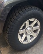
New Shoes - Nitto Terra Grappler G2

I just replaced the Winter Blizzaks with the new Nitto Terra Grappler G2s in stock 265.70.17. Toyota let me have these on their buy 3 get 1 free deal.

g2.jpg
 

Attachments

  • g2.jpg
    g2.jpg
    114.5 KB · Views: 4,932
Last edited:
nice build, i will definitely use your write up once im ready to install my arb compressor.
 
Last edited:
Nice and informative build thread. I see you have a bit of the OCD like most of us here. Just FYI, you can relocate the switches in my 2011. I can't imagine why Toyota would have changed that during the 2014 refresh. You just have to keep track of the wiring when you switch them around.
 

Members online

Forum statistics

Threads
278,304
Messages
3,554,041
Members
248,016
Latest member
Advally Service

Trending content

Back
Top