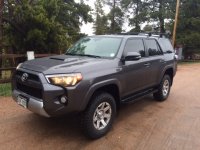
CSix Build Thread

Nice and informative build thread. I see you have a bit of the OCD like most of us here. Just FYI, you can relocate the switches in my 2011. I can't imagine why Toyota would have changed that during the 2014 refresh. You just have to keep track of the wiring when you switch them around.

Thanks Ducmonsta! Just a slight case of the OCD... lol

The factory switches i have are "keyed" in that they have groove built into the sides of the switch that keep them in only one location. I tried to relocate but could not place a stock switch in another stock switches location. That groove can be dremmeled and then I can place the stock switches in a different location. Thinking to group the lights switches in one location and move the inverter. But, I'll get around to that later.

Next up: I still need to run the rear lights wire and thinking of down the drivers side past the back into the rear and out through the grommet in the back then run the wire to the rear facing lights.
 
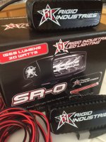
Mod #4 Rear lights: Rigid SRQs

IMG_0273.JPG

This mod is more about the actual running of wire from the back to the front then the actual light install. I have seen many posts saying to route the wire along the driver’s side but, my detailed nature (OCD) wanted to document just how it was done.

This mod really just took me two hours start to finish because I already had my power distribution box wire and switch all set up.

The rear lights are the Rigid SR-Q spot lights. Yes, I could have purchased the flood or diffused but I got the spot and have covers that I’ll make diffused. So, I have options with the way I want the light. On other vehicles, I just never had enough light out the rear when I really wanted it. These are bright. I got them on Amazon.

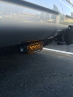
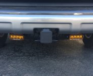
The plan is to mount them rear facing on the two M6 bolts under the rear bumper on each side of the hitch. The bolts are in the bumper and a good location and lights can be removed with the right tools easily if needed. I mounted the Rigid SR-Q on the bolts with a longer 2” M6 bolt and a metal spacer to keep the light from touching the bumper.

The wire loom that came with the lights, was cannibalized. I cut the wire a couple feet from the point where it splits to the two lights and strung new 16g wire to the front power distribution box. I did this because I already have a switch and power.

I also cut the wire so I could connect the rear wires then after running the wire loom through the grommet run the new wire along the driver’s side, inside the vehicle. I used the same color wire (in this case-yellow) as the distribution box power wire for this device and switch. (Color coordination…)

Wiring the Rear (Sorry, no pics here)
There is a grommet in the rear compartment above the spare tire that is easy to get to, easier with the spare removed. Remove two 10 mm bolts that are used for security tie downs behind the rear seats. Remove the carpeted bar behind the seats. The carpet really just pulls back, with padding attached.

Cut a hole in the grommet.

Run wires through (I ran the short end from the bottom leaving the waterproof connectors to the lights outside).

Connect the wire I’m stringing to wire that goes to lights with new wire using 16g butt connectors.

Cover with split loom and tape at the ends. This stays under the rear cargo area and the wire runs forward along the side of the rear seat

My plan for the light wires is to run under the plastic lip from the back cargo area, under the step panel in the back seat driver side, through to the step panel on the front seat drivers and up through the kick panel on the driver’s seat through the Grommet on the firewall into the engine bay. It worked.

Running the wire to the front:

The step panels really just pull off. (Really!)
Running the wire from the rear cargo area along the plastic shroud that goes from the cargo area under the rear seat worked but took a bit of effort from the fingers but it ran right to the rear step panel.

The wire really just ran under the step through to the front step panel.
The drivers front step panel pops right off too.
The drivers plastic kick panel confused me at first.
After reading Antman’s thread, well… just a good pull worked.

The wire was run to the grommet where I sliced the engine bay grommet with an exacto knife, right where an arrow was pointing, and pushed through a coat hanger.

I taped the wires I wanted to pull through the grommet to the coat hanger and pulled the wires through.

Then, popped all that plastic back in place.

Connected the black wire to my communal ground, connected the power wire to the fused relay box wire, for the switch I installed earlier. Wrapped in split loom and tucked away on the side of the engine bay.

Done.

Note to self… Plug the water proof connectors from the wire loom to the actual lights “all the way!” This will save you a bit of grief and worry that you have a short or something…

Mounted on the bolt under the bumper
IMG_0325.JPG

SRQs.jpg

The lens covers are actually yellow
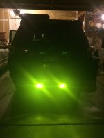
IMG_0322.JPG
 

Attachments

  • IMG_0273.JPG
    IMG_0273.JPG
    134.2 KB · Views: 1,730
  • SRQs.jpg
    SRQs.jpg
    108 KB · Views: 1,745
  • IMG_0322.JPG
    IMG_0322.JPG
    73.3 KB · Views: 1,712
  • IMG_0325.JPG
    IMG_0325.JPG
    90.7 KB · Views: 1,724
could you cut out holes in the bumper and flush mount them in the rear bumper? not sure if i would want to risk one of them getting knocked off.
 
How does that look in the rear camera? When I thought about rear lights down there I worried there would be too much light for the camera.

Actually, not half bad. I just used them backing into the garage and was surprised how the yellow covers cleaned up maybe a too bright a light. They will be mainly off road anyway. I think the diffused lights will be better for everyday. These are spots. Without the covers, they may just reach Venus.
 
View attachment 152776

This mod is more about the actual running of wire from the back to the front then the actual light install. I have seen many posts saying to route the wire along the driver’s side but, my detailed nature (OCD) wanted to document just how it was done.

This mod really just took me two hours start to finish because I already had my power distribution box wire and switch all set up.

The rear lights are the Rigid SR-Q spot lights. Yes, I could have purchased the flood or diffused but I got the spot and have covers that I’ll make diffused. So, I have options with the way I want the light. On other vehicles, I just never had enough light out the rear when I really wanted it. These are bright. I got them on Amazon.

The plan is to mount them rear facing on the two M6 bolts under the rear bumper on each side of the hitch. The bolts are in the bumper and a good location and lights can be removed with the right tools easily if needed. I mounted the Rigid SR-Q on the bolts with a longer 2” M6 bolt and a metal spacer to keep the light from touching the bumper.

The wire loom that came with the lights, was cannibalized. I cut the wire a couple feet from the point where it splits to the two lights and strung new 16g wire to the front power distribution box. I did this because I already have a switch and power.

I also cut the wire so I could connect the rear wires then after running the wire loom through the grommet run the new wire along the driver’s side, inside the vehicle. I used the same color wire (in this case-yellow) as the distribution box power wire for this device and switch. (Color coordination…)

Wiring the Rear (Sorry, no pics here)
There is a grommet in the rear compartment above the spare tire that is easy to get to, easier with the spare removed. Remove two 10 mm bolts that are used for security tie downs behind the rear seats. Remove the carpeted bar behind the seats. The carpet really just pulls back, with padding attached.

Cut a hole in the grommet.

Run wires through (I ran the short end from the bottom leaving the waterproof connectors to the lights outside).

Connect the wire I’m stringing to wire that goes to lights with new wire using 16g butt connectors.

Cover with split loom and tape at the ends. This stays under the rear cargo area and the wire runs forward along the side of the rear seat

My plan for the light wires is to run under the plastic lip from the back cargo area, under the step panel in the back seat driver side, through to the step panel on the front seat drivers and up through the kick panel on the driver’s seat through the Grommet on the firewall into the engine bay. It worked.

Running the wire to the front:

The step panels really just pull off. (Really!)
Running the wire from the rear cargo area along the plastic shroud that goes from the cargo area under the rear seat worked but took a bit of effort from the fingers but it ran right to the rear step panel.

The wire really just ran under the step through to the front step panel.
The drivers front step panel pops right off too.
The drivers plastic kick panel confused me at first.
After reading Antman’s thread, well… just a good pull worked.

The wire was run to the grommet where I sliced the engine bay grommet with an exacto knife, right where an arrow was pointing, and pushed through a coat hanger.

I taped the wires I wanted to pull through the grommet to the coat hanger and pulled the wires through.

Then, popped all that plastic back in place.

Connected the black wire to my communal ground, connected the power wire to the fused relay box wire, for the switch I installed earlier. Wrapped in split loom and tucked away on the side of the engine bay.

Done.

Note to self… Plug the water proof connectors from the wire loom to the actual lights “all the way!” This will save you a bit of grief and worry that you have a short or something…

Mounted on the bolt under the bumper
View attachment 152784

View attachment 152781

The lens covers are actually yellow
View attachment 152783

why didnt you just tap into the backup lights and call it a day? the back up light wire is the red one on the 2013 when you take the light off.
 
why didnt you just tap into the backup lights and call it a day? the back up light wire is the red one on the 2013 when you take the light off.

The Rigid SR-Q's are way too bright to have on every time I put the truck in reverse. I only want them to come on via a switch. That's why they are run into the power distribution box with a AOB switch.

If i go with flush mounted at a later time, I'll get something a bit less intense.
 
I just connected up the dash illumination for my switches . I originally set up a wire in the wiring harness for dash illumination but had not yet connected it. Many other posts noted the use of the green wire on any stock switch. So, I tapped into the green wire of the defroster switch. This wire does give power to the illumination but does not vary the brightness as the dash rheostat is changed. I did not test the other switches wires.

I also found a switched (accessory on) empty fuse location in the fuse box under the dash on the driver’s side so the compressor will only be turned on with keyed power.

The AOB switches fit really well.
View attachment 151641

I love this build!! I have just fabed up my harness and installed all of the AOB switches.

I couldn't find the dimmer circuit at the wiper defrost switch either, but I checked the circuit with the switch disconnected so I will try again with it hooked up later. For now I tapped into the grey wire direct at the rheostat it measured 0 to 4.95V based on dimmer adjustment min max.


It tested all good except...the circuit is intended for the cluster which has active lights all the time. So, the switch lights are always on yet still dim with the dimmer....Always something :frusty:

 
Last edited:
I love this build!! I have just fabed up my harness and installed all of the AOB switches.

I couldn't find the dimmer circuit at the wiper defrost switch either, but I checked the circuit with the switch disconnected so I will try again with it hooked up later. For now I tapped into the grey wire direct at the rheostat it measured 0 to 4.95V based on dimmer adjustment min max.


It tested all good except...the circuit is intended for the cluster which has active lights all the time. So, the switch lights are always on yet still dim with the dimmer....Always something :frusty:


Awesome research. I was wondering if a connect to the dimmer directly would work. After a week in CA and a ride up Highgrade today, i'll try to pull the multi meter out tomorrow and continue on a dimming quest. Thanks!
 
Turquoise Lake

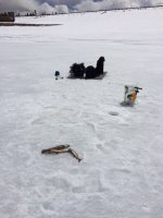
We hit Turquoise Lake in Leadville last Sunday. Ice Fishing.
IMG_0331.JPG

Ice was about 1.5 feet in places but had some thin areas of 4-6. So, worms just were not appetizing for about an hour. This was the first 15 minutes of switching to shiners. We caught six lake trout but the limit was two per so we let the two smallest go.
IMG_0328.JPG
 

Attachments

  • IMG_0328.JPG
    IMG_0328.JPG
    114.8 KB · Views: 2,367
  • IMG_0331.JPG
    IMG_0331.JPG
    121.2 KB · Views: 2,386
Mod - Presta or Shrader Air Inflator

This mod came into being when I needed to mount a Schwable Racing Ralph 29er tire to a Fulcrum Red Metal UST, tubeless... and my home air compressor died.

So, I used the ARB compressor I mounted in the truck, and it sort-of worked. But, I did not have a presta pump head and the shrader converter let too much air pass by to really set the bead. So, I removed the core and used a generic rubber fitting and still set the bead and I still needed to pump the tire up by hand... after fitting the core back in.

This made me think, I need an air gauge inflator that quick connects to my air hose and can handle either shrader for truck tires after 4 wheeling or presta bike tires for my road or mountain bikes, like on group rides, setting tubeless tires, etc...

Have you ever seen a presta pump head for an air compressor? I found all sorts of shrader heads. There is a presta Park Tool for $120 (yeah right) and another "Presta.com" one for close to $50. But, none I could find could handle either Presta or Shrader. Now, most new bike pump heads can handle both. But, enter another wrinkle... the Trail wheel protects its stem so the bike presta head is too big to fit on the Trail wheel's stem!

So, tonight... it's snowing and the wife is playing legend of Zelda... Time to Mod!

I got a specialized pump head ($4.95) from Bikesource, a length of air tube from an old pump.

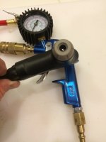
I bought a Campbell Hausfeld shrader based air gauge head for less than $15 from Amazon. It also goes to 150psi. I run my road tires at about 115. A similar ARB gauge only goes to 100.

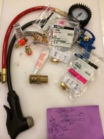
I took it apart and noodled how I was going to add 1/4 NPT quick connects so in could interchange Presta or Shrader hoses and drew up a quick diagram.

The build: The unit needed a 1/4 NPT quick connect at the base for the main air hose, two more on the hoses (presta and shrader) and three reducers from 1/4 NPT to 1/8, and a 1/8 male to male connector to connect to a 1/4-1/8 reducer for the pump head quick connect. I also had a quick fitting for the heads on hand and some permatex thread compound.

Parts and diagram:
IMG_0338.JPG

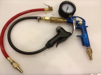
Complete. The air gauge tool connects to the air hose and has two pump heads attached by 1/4 NPT quick connects. The black air line is for bikes and the red for automobiles.
IMG_0339.JPG

This pump head is both presta or shrader but will not fit a Trail wheel. The Trail wheel's stem is protected from rocks and this head will not fit. But, works great on bike tires.
IMG_0340.JPG

This rocks! I just filled the wife's almost flat 29er tires in about 2 seconds using the ARB air compressor. Total Cost: $32 and it handles anything.
 

Attachments

  • IMG_0338.JPG
    IMG_0338.JPG
    122.6 KB · Views: 2,342
  • IMG_0339.JPG
    IMG_0339.JPG
    78.1 KB · Views: 2,385
  • IMG_0340.JPG
    IMG_0340.JPG
    91.9 KB · Views: 2,360
Last edited:
Mod#5 – Bilstein 6112/5160 Suspension aka TRD Pro Suspension

Ok, so I knew I was getting a 4Runner and I knew I was going to upgrade the suspension. But… upgrade to what. I liked the specs of the TRD Pro suspension even before Bilstein rolled out the 6112/5160 suspension combo. I considered other suspensions, the usual suspects… and researched from the suspension thread, builds and general comments. I ended up with the 6112/5160 combination for what I wanted… overall 2” lift, ability to go larger, well built for off road great on road manners and adjustable.

My wife would only get the 4R with a locking rear diff (She’s wheeled in my CJ) and I wanted the Trail edition Premium but the TRD Pro was coming out… Well, I have to have my sunroof… sorry TRD Pro… Let the build begin. In the end, I’m glad I went this route because I have the truck I want with the lift I want and all sorts of potential.

IMG_0376.jpg

I’ve replaced several suspensions on Jeeps, thought I’d do this one too. But, I just got all the parts in and ouch… I have a cold… and then there’s Mothers day coming up with more rain in the forecast… and I wanted to put it in as soon as I could. The dealer can do it with their best mechanic…
Oh wow, my man card is in jeopardy… Wife says, “but look at all your mods… and you’ve already done stuff like this…” So, man card still intact. I paid $$$.

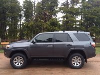
Now, I actually like my 4Runner stance especially when I have a dog and a bunch of gear riding in the St John’s area. Many people like the level look. I like it too. But, I really just want the stock look but 2” higher. I was a bit apprehensive going 2” all the way around because no one had done it yet with the 6112’s/5160s with springs… documented… time to break new ground.

There are many combinations of equipment, vehicle options, and suspensions that will affect the height of the lift as well as the drivability. Every application really is different. The cost of failure is high. You really don’t want to rework or pay twice, etc. Time to do my homework.

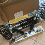
The 6112's installed in the front at the third C clip setting look to have a ~2" lift on a 2015 T4R Trail. There are 5 settings. In inches the actual values noted: 1=0, 2=.95, 3=2.0, 4=2.5 and 5~3.0. This differs greatly from the Bilstein published specs. Several members forged ahead and found this information. I have only seen installs of 2nd, 3rd and 4th clip settings. No #1 or 5 as of yet on a 4x4. So the numbers for those here are estimates. So, at the third setting, I can still increase the setting if I feel the need or add a winch bumper.

The rear 5160's are a remote reservoir shock and are not supposed to add any height. Reading through the posts, there may be something to the 5160’s adding half an inch or so. Then, I took all builds thusfar side to side, and noticed many people used the Sway away 1.5 spring. I did some checking and calling and found the SAW springs indeed give 1.5 inches on Runners with 3rd row seats. To me, that means, maybe 2” on non third row vehicles? A discussion with Bilstein seems to confirm.

I wanted a spring that worked with the 5160s and was not too squishy or hard, noting [MENTION=77958]Zeusmotorworks[/MENTION] comments on stock springs (thanks Zeus). I talked with Bilstein and Total Automotive on the spring rates and what’ll work best with the 5160. I decided on the Icon 2” spring for my application. Now, it seems like all springs are made by Eibach… Guess Icon will have to do.

Plan: First, Install the 6112’s up front at the 3rd clip setting for ~2” lift. Then, install rear springs (not spacers) for a 2” increase too.

I had the local Toyota dealership perform the install. (yes, man card in jeopardy). But, the tire guy and parts guy are cool and service was great with another issue after a major hailstorm… I’m told the mechanic had a bugger of a time with the increased size of the rear coils and I was glad I was not on my back with a cold, under a cold wet 4Runner applying brute force and ignorance principles to stubborn rear coil springs… Job looks real good. I will rearrange the remote reservoirs but, the underside is muddy and wet and the weather ain’t getting better until next week or so!

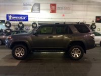
Tires are Nitto Terra Grappler G2's. I'd say I came right in at 2".

Actuals: Measured after 50 or so miles up Highgrade road to Conifer and back.

Before After Lift
L Front 34.5 36.5 2.0"
L Rear 37.0 39.0* 2.0"
R Front 35.0 36.5 2.0"
R Rear 36.75 39.0* 2.0"

(Actually, 39 1/8" but i rounded...)

FullSizeRender.jpg

View attachment 156623

Notes:
I'm amazed that the side to side "lean" disappeared after the lift. [MENTION=103267]Saker[/MENTION] noted similar equality between the sides.
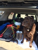
No lift noted from the 5160s, only the springs. My dog is in the back and it came out 2 inches exactly. Now, he needs to jump a tad bit higher...
The mechanic said the Alignment came in perfect. (I do not have the sheet)

We took it for a drive up High Grade Road. Yes, it's pouring out... a real good test. Driving has a much improved feel. Tracking, bumps are indeed handled better (the driver alert bumps kinda melt away). IMHO, this is how the 4Runner should be stock. Yeah, suspensions are subjective and definitely won’t say this is the best thing since sliced bread sprinkled with unicorn dust but, really... I do like.

IMG_0393.jpg

IMG_0391.JPG
 

Attachments

  • IMG_0376.jpg
    IMG_0376.jpg
    62.3 KB · Views: 2,543
  • FullSizeRender.jpg
    FullSizeRender.jpg
    93 KB · Views: 2,509
  • IMG_0391.JPG
    IMG_0391.JPG
    132 KB · Views: 2,882
  • IMG_0393.jpg
    IMG_0393.jpg
    55.8 KB · Views: 2,961
Looking good brother... glad you also got your desired result. I'm playing with the idea of selling my front 2.5 Camburgs and rear Icon 2.5 piggies and doing the same lift on my FJ now. Only concern is the heavy ARB bumper and Warn M8000 winch. Then again, on the FJ the front is dialed in closer to 2" than 3" of lift for travel and to keep the center of gravity low.

A set of front/rear Spidertrax 1.25" wheel spacers raises the roll center and makes the Wife's 4Runner corner flatter than stock ever did before the lift. She loves it, I really like it.
 
Last edited:
It looks great and much better than I expected when you posted what you were putting in, I can see it being great for a load in the back. the last truck with 5100's up front and icon springs in the rear looked much different. Must be the 6112's...
 
Awesome research. I was wondering if a connect to the dimmer directly would work. After a week in CA and a ride up Highgrade today, i'll try to pull the multi meter out tomorrow and continue on a dimming quest. Thanks!
Did you figure out the dimming? My dad and I installed the backup camera and light bar buttons this weekend and got it to dim properly with the others. If you still need it I can get you the wire colors we tapped.
 
looks good, I thought it was going to be much more ass high with those coils... if they settle it will be perfect
 

Members online

Forum statistics

Threads
278,305
Messages
3,554,042
Members
248,016
Latest member
Advally Service

Trending content

Back
Top