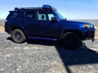
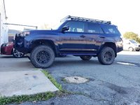
Dades Bluegirl build

Went over to the shore and got my sliders. now they are installed. 1 more step towards the completion of my dream vehicle (yes many steps still to go).

I know they will never look this nice again. I accept the will get dented, scratched, scuffed... I am okay with that.

Nice work. Any special instructions or tips about how the sliders mount up. Picked up a set of Mobtown sliders last weekend for the wife’s 4runner, not much to go on.
 
Nice work. Any special instructions or tips about how the sliders mount up. Picked up a set of Mobtown sliders last weekend for the wife’s 4runner, not much to go on.

pop all the plastic hole covers off. The holes will line right up with the frame on where you bolt them in.

if you have the plastic steps. id put a rubber washer and put the screw back in where you removed them to get the sidestep off.

If you have any questions, Shot Joe and Email, awesome people, very friendly and helpful.
 
Communications CB\GMRS

Got my Comms. My idea/goal for this was to be able to use comms while driving, but also out of the rear while camping (base camp ops idea). I did run a concept test prior to install.
Thanks to Anand for answering some questions I had regarding the equipment.

*** This will not work for all radios ***

Equipment:
Radios:
.. CB: Uniden CMX760 *
.. GMRS: Midland MXT275
Antennas:
.. CB: Browning NMO CB antenna *
.. GMRS: Larsen Pulse W145B
.. Mounts: Tram 1247-B (x2) *
.. Antenna adapter: DHT PL259 UHF male to UHF mini female (x2) *
.. Antenna mount cap: Tram NMO rain caps (x2) *
Comm Lines:
.. Rj45 splitter: RJ45 network splitter 3 port (x2) * (explain why 3 vs 2 on the section with the instruction**)
.. Cat7 cable: 3' (x2) * #
...................15' (x2) * ##
.. Mic ports: RJ45 Radio Mic Pass through (x4) *
.. Port mount: CH4x4 3 port Toyota push switch small *

* all items stared : purchased from the mighty Amazon.
# cable lengths will very based on the location of your head unit.
## anything longer the 20' for GMRS I have found picks up RPM feed back


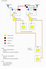
This is my comm plan. (for you electrical people and diagram experts I apologize for not using proper symbols). Both my head units are just boxes, everything is controlled through the mic. Since it is just a data cable, I split it. This way I can use when in the back of the vehicle while at a camp site (kinda like for base camp ops) or from drivers seat while on trail.
 

Attachments

  • comm diagram.jpg
    comm diagram.jpg
    105.9 KB · Views: 1,204
Last edited:
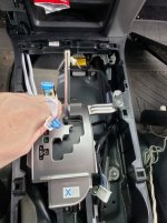
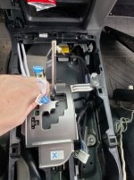
I installed my head unit in front of the shifter under center console. Yes there is a big enough cavity there to mount both head units and cables.
When removing center console.

*** Before you take it complete up. reach in and disconnect the 4WD selector (front) and system cable (passenger side middle) ***

Find a location you want to install your head unit. Measure the distance you need for your cables (piece of string and run it how you want to run comm cables then add 2')
 

Attachments

  • 20190322_130924.jpg
    20190322_130924.jpg
    130.8 KB · Views: 1,199
Last edited:
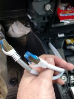
Mark you cables if you are running both GMRS and CB. If you are only running one - no need to.
 

Attachments

  • 20190322_140858.jpg
    20190322_140858.jpg
    95.7 KB · Views: 1,187
Then I removed the door sills, and rear lower 1/4 panel. For the write up on that (not my work but great write up) go here:
Rear cargo panel removal (where sub would go)

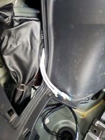
Ran both of the 15' cables. Started from the front and ran to the rear. I had about 1' spare each side.

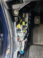
From the front. feed from center counsel to dash. from dash over and down to drivers side sill.
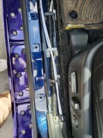
At the "B" piller, I just pushed the cable under the plastic molding.
Then feed under the rear passenger molding.
Feed the remainder of the cable to access panel for tire tools. leave ends accessable.
 

Attachments

  • 20190322_130924.jpg
    20190322_130924.jpg
    130.8 KB · Views: 958
  • 20190322_131041.jpg
    20190322_131041.jpg
    114.3 KB · Views: 965
  • 20190322_131044.jpg
    20190322_131044.jpg
    123.4 KB · Views: 961
  • 20190322_134634.jpg
    20190322_134634.jpg
    98.9 KB · Views: 960
Last edited:
At this time I put back the molding. (no pics needed for that)
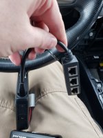
Attached the rj45 splitter to each head unit. **( The reason for the 3way splitter vs 2 way splitter. 2 way only seperates the 8 lines in the cable so you go from 1M 8pin to 2F 4 pin. The 3 way goes from 1M 8pin to 3F 8 pin).
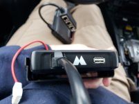
mounted the 2 head unit together.
3m molding tape and mounted the 2 rj45 splitters on top of the top head unit.

Mounted the Head units to the vehicle.
I placed them so the power and antenna cpnnections would be facing the source. This allowed the splitters to be placed on top and the data cables routed cleanly to destinations.
cleaned up the loose cable. (Velcro straps)

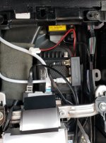
Power came from the fuse relay box I installed last year. All the wires were ran, just needed to select a line and place in the appropriate fuse (5amp each)
 

Attachments

  • 20190322_103447.jpg
    20190322_103447.jpg
    98.1 KB · Views: 965
  • 20190322_103508.jpg
    20190322_103508.jpg
    82.3 KB · Views: 959
  • 20190322_143657.jpg
    20190322_143657.jpg
    114.3 KB · Views: 956
Last edited:
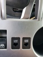
Next was to remove the 2 blanks in the center console (I have base SR5 with nav so I have this availability).

** If you don't have this, you can buy a Toyota push button (Small) mount and cut out a hole and mount on dash or side of console or front of center cubby. your ride your call. **
 

Attachments

  • 20190322_143648.jpg
    20190322_143648.jpg
    85.8 KB · Views: 957
Lets go to the rear of the vehicle and finish up the back.

Took my 3 port Toyota push button (small) mount and marked the location I wanted to install it in. I went with the drivers side because I didn't want my com cables on the inverter that is on the passenger side. Also down the road when I add a fridge - it would be harder to plug and play.
I went with 3 port mount because I will be adding a USB port later.

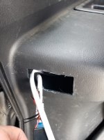
Marked and cut out the hole. Cleaned the edges
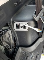
Screwed in the port mount
Reached into the tool copartment and fed the cable through the corresponding holes in the mount.
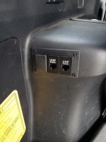
(GMRS driver side/ CB passenger)
plugged into the mic pass though device.
Pushed those into place. They are a very tight fit.

Took the blank from up front and pressed into the far left spot for now.
 

Attachments

  • 20190322_150414.jpg
    20190322_150414.jpg
    97.6 KB · Views: 965
  • 20190322_150410.jpg
    20190322_150410.jpg
    99.8 KB · Views: 960
  • 20190322_150812.jpg
    20190322_150812.jpg
    94.4 KB · Views: 962
Last edited:
pop all the plastic hole covers off. The holes will line right up with the frame on where you bolt them in.

if you have the plastic steps. id put a rubber washer and put the screw back in where you removed them to get the sidestep off.

If you have any questions, Shot Joe and Email, awesome people, very friendly and helpful.

Appreciate the feedback! Thanks
 
Finished the comms. Antenna mounts put on. Permanent power source for the head units wired in.

Antenna mounts are NMO trams - ran through the passenger side firewall grommet.

Tested from about 3/4 mile from my house with trees, and a lot of power lines. GMRS worked great. CB weather alerts cam in good.
 

Attachments

  • 20190326_143810.jpg
    20190326_143810.jpg
    138.6 KB · Views: 923
Last edited:
Love the color and build progress. I would love to see it in better lighting showing the front end better. A lot of shade in most pics.
 
So you just cut the holes and glued RJ45 jacks to the back of the "blank"?

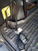
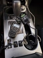
Yes and No. I used no glue. In the front I did no cutting. The RJ45 jacks are just fancy barrel connectors. They have tabs so they just lock into place in the slots (I have a base SR5 so I have 8 blank slots to use).

For the rear I did cut the hole. I also used a 3 port, port mount from CH4x4 . That I bolted to the panel. The RJ45 ports just clip in like they did in the front.
 
Here is front and rear completed.
 

Attachments

  • tmp-cam-7219283256878330835.jpg
    tmp-cam-7219283256878330835.jpg
    23.9 KB · Views: 489
  • tmp-cam-4137070341864341186.jpg
    tmp-cam-4137070341864341186.jpg
    18.3 KB · Views: 484

Members online

Forum statistics

Threads
278,316
Messages
3,554,113
Members
248,016
Latest member
Advally Service

Trending content

Back
Top