E-Fan swap.

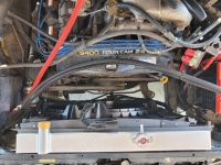
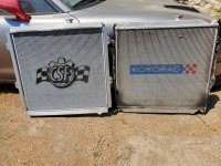
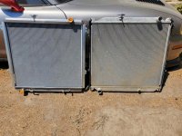
Ok so progress has been made today, got the csf radiator in. It's massive compared to the koyo. It looks bigger then what the specs I posted in the 1st post. The csf doesn't have the ears like the oem mounting, but it's not hard to install. Start with the top bolts first. Well there was some strange stuff going on in the neighborhood so I was a bit distracted and forgot to put the sealing foam on the shroud. Of course I filled the system with coolant too, 2.5 gallons.so I have to remove the upper hose and reseal the shroud with the foam I forgot. Sigh. Wiring should be quick. I do have to move my winch master switch, but have a good location for it. Between the grill and top radiator support.

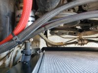
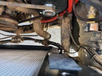
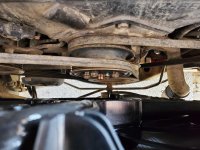
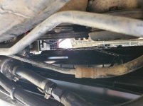
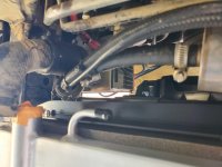
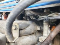
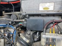
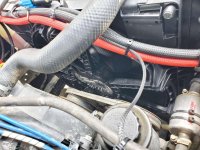
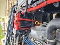
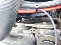
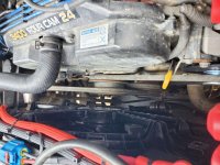
See pics for clerance of pulleys and other stuff. Was going to eliminate the whole fan mount, but forgot there was 2 belts on it and didn't want to spend any more time or $ to figure out what belt I needed. The fan clutch base is 6mm thick and it a m8 stud. So some spacers for that should be here tomorrow. Fan controller will be on top of air box. I'm tired and pie eyed and hungry, so enjoy the pics.
 

Attachments

  • 20250716_151316.jpg
    20250716_151316.jpg
    135.5 KB · Views: 377
  • 20250716_151322.jpg
    20250716_151322.jpg
    134.4 KB · Views: 376
  • 20250716_154634.jpg
    20250716_154634.jpg
    139.6 KB · Views: 375
  • 20250716_154645.jpg
    20250716_154645.jpg
    132.4 KB · Views: 371
  • 20250716_154717.jpg
    20250716_154717.jpg
    123.5 KB · Views: 373
  • 20250716_154723.jpg
    20250716_154723.jpg
    119.3 KB · Views: 371
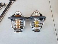
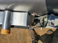
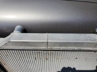
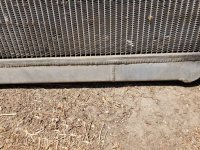
Pics of radiator. And one interesting thing I found. Since I was due for a coolant swap, I changed the t-stat too. Be careful where you get toyota parts from. I don't know where I got the t-stat I took out from. But the replacement is from toyotapartsdeal. com. Look at the difference, and the new one is stamped with teq. New one is on left. Also, yes the csf has massive end tanks compared to the koyo, but it's the core size that matters.

The koyo is 100% a triple pass radiator, see the division welds. From what I have read regarding triple pass rads is that you need a high flow water pump. Much higher then stock to use the rad correctly. A dual pass can function correctly on a stock pump, a cross flow radiator would be awesome too, but custom rads are serious $.

Two things I do not like about the csf for sure: the top hose hump, great place to trap air. Second is the non oem mounting system, sure you can squeeze a row or two more tubes but it's really odd and leaves a gap that air can bypass the actual core. Which reminds me I need to run a bead of silicon to seal that up. They didnt need to make the width of the mounts that wide. So if you use the csf with oem shroud and fan, it will push the shroud further behind the fan. That is a bad thing. There needs to be a % of shroud depth vs fan clerance. It may be 1/4 inch or more thick. Think air is lazy, any area with no resistance, it will take that path.
 

Attachments

  • 20250716_131143.jpg
    20250716_131143.jpg
    124.8 KB · Views: 371
  • 20250716_143009.jpg
    20250716_143009.jpg
    136.1 KB · Views: 373
  • 20250716_143039.jpg
    20250716_143039.jpg
    136.9 KB · Views: 378
  • 20250716_143044.jpg
    20250716_143044.jpg
    140.3 KB · Views: 376
  • 20250716_143034 (1) (2).jpg
    20250716_143034 (1) (2).jpg
    131.7 KB · Views: 375
  • 20250716_142951 (1) (2).jpg
    20250716_142951 (1) (2).jpg
    131.7 KB · Views: 372
Last edited:
This is a long wall of text, sorry.

TL : DR - I missed the description on my issue in the instructions (thanks to whatever it is I have wrong with my brain), and now need to switch to the RTD sensor. If it still doesn't work, I'll put the mechanical fan back on (my vacations is ending soon) and order a different fan controller. This is all a process of testing and learning what works. I'm not giving up, lol not even close. This fan works and is amazing to say the least. If you want the blow by blow read below:

Alright, figure I'd update with a bit of info. Got the foam sealing redone today and finished all the wiring for the fan and it's controller. Did the fan test to make sure I have all the parameters correct. Then I set out to "learn" the widget man's fan controller (will describe later).

The fan test has 2 modes. Switch 7 on, sends the fan to 90% of its power. Let me tell you it does, and it move serious air, more then a fully locked up fan clutch. Downside, pulls nearly 75 amps iirc. So to my knowledge there is no alt capable of putting out that amperage at idle. So I had to raise the throttle to get it the proper juice. Good news is, there is zero reason it should ever go on full blast unless you are testing it like I did (and what I'll describe later).

Switch dip switch 1 to off and the fan will drop to the slowest speed possible. It did. So I have all the correct dip switch settings. Fantastic.

Ok now, I have all the repair manuals for the 4runner and iirc it doesn't give the voltage drop in resistance (I'll check tomorrow) as Temps increase. The minimum set point between fan on (slow ramping speed) to full boar for the widget man controller is 30mV (milivolt) with a 5v reference signal (what toyota uses on the 5vz). Issue is, there is from what I can tell on the ecm temp sensor (not gauge) is a somewhat flat spot between 190°f and 220°f ie the mV is less then 30mV between those temps. So for a tiny like 30 seconds my engine got to 220°f. I shat a brick, jammed the widget man into full speed test mode, and it cooled off the engine, no joke in under 30 seconds!! Back down to 188.

But still, I was perplexed as to why it didn't accept the set points I taught it. (190 fan on and 205 fan full speed). After that one stint of 220 freaked me out so I never let it get any hotter then 205 for an extremely short time (think heat soak on a 110 summer day). Thinking I did some sort of set up wrong, I cleared the memory and tried again. On set point 188 and full speed 205. Ok fantastic, it took the settings! Great! Oh snap the tstat opens around 180 and the upper hose where the ecm's temp sensor is located once engine is up to temp never goes below 190. Crap, now the fan never shuts off. Ok well it works for now, moved on to the other tests. Ac fan turn on, bam works like a charm, maybe to good lol. Sweet. I have the fan set to 50% power plus what ever fan speed it is currently at.

My ADHD and OCD (CDO for those that must have it in alphabetical order) won't leave well enough along. Car has cooled off significantly now. Try relearning again. Failed. Well turns out the instructions tells you if you can't set the on and hi speeds, the mV drop isn't enough.

Here is what caused this situation: I have something that blanks out stuff when I'm reading things, and randomly capitalizing letters when I'm hand writing things (have had this since pre-school) dont know or remember what its called. Well there was a snipit in the instructions that describes the exact situation I'm having, to a T. I felt like a total idiot for a lack of a better term.

So sorry for the wall of text. I'm going to switch to the widget man's RTD (FPMS) temp sensor tomorrow and bolt it to a stud on the upper water neck. Then go through the relearn process again. Looking at the rtd's temp to resistance to 5v drop between middle of 185 and 194 (190 on my scangauge) ~1.115v and 203 .96v should be close to 130mV drop. It should work. I'm afraid to set the max on speed anywhere near 215-220. But then again when I did hit 220 the dash temp needle was still dead smack in the middle.

One other note, the new tstat works 100% better then what ever I had in there. I mean, scan gauge hit 188 and the tstat was already open. Never had that happen before. So that is where I'm at now.

 
Last edited:
Random thought on cooling fan systems...

I would use the radiator outlet temperature, not the engine temperature as the reference point for my cooling fan control. Many/most/all OEMs do it this way - some sort of secondary temperature sensor/sender/switch on the bottom of the radiator, water INLET neck, etc.

The idea here is to just provide a 'cool' coolant source, along with the hot bypass path for the thermostat to do its job with. Even the stock mechanical fan *kinda* works this way - the fan clutch 'senses' the air temperature through the radiator/condenser - not the engine temperature.

At that point, you can set the fan on/off temps to something like 170*F start, 195*F max, which will keep some 'headroom' in the cooling system for short bursts of heat that can be dumped into the radiator. It should keep the fan running a bit more often, but at lower speeds, using the heat capacity of the coolant as a temperature 'filter' to store and later dissipate heat energy.

You can get temperature sensor adapters you can put in the lower hose to get the sensor in the right place. Here's what I did on a motor swap in one of my other Toyotas to keep the OEM e-fan control system intact:

FhpJwySh.jpg

(OEM fan temp switch + ground wire)

-Charlie
 
[MENTION=139000]phattyduck[/MENTION] yes I was going to go that route as well. Looked into it for a long while as well. I did contact almost every pwm fan controller company and they advised me against that type of system. Their reasoning is, in the event of a coolant flow failure (be it water pump, t-stat, or something else) the coolant flow becomes stagnant, or as they called it hoses/rad goes cold. And an inline sensor like that would allow the engine to overheat due to no flow.

I have had this happen in a old 1991 vw jetta. Water pump failed and I overheated the engine.

Not knocking that set up at all. And I know it works well, we have used it many times on our rally cars and on my motor swapped Cressida, but those were conventional fans not pwm fans. Thanks again Charlie!

Here's a quick update:

The FPMS2 or RTD sensor from widget man fixed the issue. The oem ECT for the ecm milivolt is way to close together at higher temps. I didn't want to have to make the max speed at 215 degrees. So I woke up early today to get started on this as I don't have any more free time. Wired in the RTD sensor, mounted it to the back stud of the water outlet. Ran the wire far as I could get it from the plug wires, hooked it up to the controller and proceeded forward.

Cleared the current set points and fan ramp up learning profile. Rechecked everything. Turned ignition on, perfect, solid red led (no set points stored). Warmed the engine up, this time I just let it idle to fan on set point. Hit 193 degrees and hit the green button. Boom, solid yellow led (on set point saved). Hold the red button (max speed turn on) fast red blinking led. Got to 206 degrees, hit the button, bam slow green flashing led, fan on indication. Fan then went to full blast, engine cooled in a few seconds down to 190, fan turned off. Engine hit 193, fan came on, cooled down to 190 and shut off. I let the engine idle like this for about a hour, fan cycled perfectly. Checked ac turn on, fan came on. Perfect. It turned out the fan kicks on exactly when the tstat opens. I didn't plan that it just happened.

Honestly I was seriously thinking of just putting the fan clutch back on and get a different controller (leaning towards the lingenfeilter jeep version link in first post). But gave it one more shot with the RTD sensor. I did watch the input voltage from the RTD and it is way more precise then the oem toyota ect sensor.

The RTD's output is nice and linear. No big voltage drops or shifts. Even better thing is if you use widget man's fan controller and the RTD sensor you can mount it virtually anywhere on the engine. It maps a custom tempature profile (pwm to send to fan) between on point and max. When it was doing this you can hear the pitch of the fan changing. After a hour, it had a profile and was steady.

So, to sum it up. It's working good as it sits now. I will test drive it tomorrow to make sure it is all working while driving etc. I misplaced my amp meter, but I want to see and update this thread with amp draws. I know when it soft starts and is at lowish speed it drops the voltage .1v (14.5v to 14.4v at battery).

I'll do periodic check ins to update how this is working. But a short rundown of what I have as of now:

6th gen camaro ss pwm fan
Widget man's pwm fan controller
Widget man's FPMS RTD sensor in NTC set up (voltage drops as temp increases)
90a fuse for fan
8awg wire for fan motor, direct to battery, no relay needed due to soft start
All other wire is 16 awg
RTD wire is like 30 awg so I adapted it to 20 awg then 16awg.
 

Attachments

  • 20250718_135929 (2).jpg
    20250718_135929 (2).jpg
    134.4 KB · Views: 326
  • 20250718_135936 (2).jpg
    20250718_135936 (2).jpg
    138.6 KB · Views: 328
  • 20250718_135941.jpg
    20250718_135941.jpg
    137.5 KB · Views: 325
  • 20250718_135947.jpg
    20250718_135947.jpg
    138.5 KB · Views: 326
  • 20250718_135953.jpg
    20250718_135953.jpg
    126.8 KB · Views: 323
  • 20250718_140007.jpg
    20250718_140007.jpg
    135.2 KB · Views: 329
Last edited:
[MENTION=139000]phattyduck[/MENTION] yes I was going to go that route as well. Looked into it for a long while as well. I did contact almost every pwm fan controller company and they advised me against that type of system. Their reasoning is, in the event of a coolant flow failure (be it water pump, t-stat, or something else) the coolant flow becomes stagnant, or as they called it hoses/rad goes cold. And an inline sensor like that would allow the engine to overheat due to no flow.

I have had this happen in a old 1991 vw jetta. Water pump failed and I overheated the engine.

Not knocking that set up at all. And I know it works well, we have used it many times on our rally cars and on my motor swapped Cressida, but those were conventional fans not pwm fans. Thanks again Charlie!
Interesting argument from the fan controller guys (it is opposite how most OEM fan setups work). You still need temp sensing for the engine directly to make sure the thermostat is working correctly, of course - but no amount of fan is going to fix a bad thermostat or other coolant flow issue.

So, fan controller based of radiator temperature (what the thing is actually controlling!) and engine control and dash indicators based off the actual temperature of the engine would still be how I would do it.

That said, how you did it will still work just fine!

When you started this, I did a bit of my own research and didn't find one PWM fan controller that worked how I would like one to work... whether it was the control scheme, the way you 'programmed' it, the mechanical layout (electrical connections, etc.)... and most seem to turn the fans on quite high (PWM %) for AC, when most OEM fan setups use about 25-50% speed for the 'low' AC fan setting. The Camaro PWM fan is an awesome option though! Previous e-fan options were all much more of a challenge to control and power, especially variably.

-Charlie
 
Yes and I see your point. Nothing will help a stuck/broken tstat (unless stuck open).

The control scheme is one reason I chose the widget man's fan controller. It creates a ramp profile based on your turn on set point and max fan point. The ac is selectable between 50% + current fan speed. The one other I know has done that is the lingenfeilter jeep modded one. They had them program it to be 50% fan when ac is on. Now delta pag offers that in their current fan controller, but I'm not 100% sure it will control anything but their proprietary fans, which sound to good to be true. Looking at their wiring diagram it does look possible to use it in what I'll call a OEM+ set up.

Yes oem's these days have temp sensors everywhere. Water outlet, inlet, after tstat, radiator, t/b etc. I'm glade I'm left the auto industry well before all that stuff. Lots of that is necessary to regulate the emissions (can only run the engine so hot before it melts, Mazda sky activ cough cough).

The other thing I had to keep in mind is I'm not running a stand alone engine management system. So I needed the fan controller to be stand alone. I wanted less tech, to keep the system as simple as possible, and not cost a fortune. I will be buying another widget fan controller and RTD sensor for spared. About 80 bucks or so. Any other fan controller is close to 300$+.

There are always trade offs. I did compromise on the fan controller. I did want complete control over the pwm % to engine temp and vehicle speed. I mean you don't need the fan on at highway speeds w/ac on. But that territory is attained via stand alone ecm. That would simplify the wiring significantly. The pwm signal to fan, B+ and ground to fan then your done. All the curves and set points are done via ecm. Similar to oem.

Anyways, that's all I know as of now lol.
 
It hurts to say this, but while I went for a test drive today they e fan system didn't work, well sort of. I did not overheat the engine (202 was the hottest). I'm guessing while at speed and with the fan on and with it spinning blocks the natural forced air through the grill. Causing a sort of stagnation of airflow. Sitting it works perfectly. Driving not so much. And what really sucks is all the stuff I did, I just took off today lol. Crap happens. That was a wasted stacation sigh.

Edit - did a few drive cycles yesterday and last night, it seems the air bubble that was stuck in the passenger top of the radiator is gone now. Still though I'm bummed about this.
 
It hurts to say this, but while I went for a test drive today they e fan system didn't work, well sort of. I did not overheat the engine (202 was the hottest). I'm guessing while at speed and with the fan on and with it spinning blocks the natural forced air through the grill. Causing a sort of stagnation of airflow. Sitting it works perfectly. Driving not so much. And what really sucks is all the stuff I did, I just took off today lol. Crap happens. That was a wasted stacation sigh.

Edit - did a few drive cycles yesterday and last night, it seems the air bubble that was stuck in the passenger top of the radiator is gone now. Still though I'm bummed about this.

I'm sure I speak for many but I admire your drive and skills. Too bad it didn't work out the way you hoped.
 
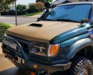
Don't recall seeing a pic of the front of ur 4runner but didn't you say you have a plate bumper, large trans cooler, winch and other additional weight? Is it possible you just have to much blocking air flow and/or to many stacked coolers? With the added weight and how your using the vehicle could the radiator just be undersized now? just ideas and thoughts, maybe your fan and controller are not the issue, or at least not the solo issue.
 
[MENTION=373697]Endlessblockades[/MENTION] thanks, I'll come back to this in a while. I wasn't able to get the stuff I needed to get done over this staycation, so those come first now and this is on the back burner.

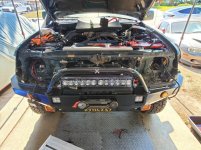
[MENTION=222826]clearock[/MENTION] yes I have a pic. I'll post it here. Well I didn't have an issue with the stock set up with all the stuff in the way. The electric fan had no issue pulling air through the cooling stack, I'd venture to guess about 10-20% more air then the fan clutch. Dead serious this e fan pulls massive air! Also the 6th gen ss camaro this fan came off of, it's cooling stack is 3-6 inches thicker then mine. Also everything is foam sealed. Forces air through heat stack vs around. For testing, I ran 2 weeks without the front light bar in front of the grill. I saw zero difference in temps, both on street and freeway. The first pic is what I had to take off to get to the lower radiator bolts. That or take the bumper off.

The issue I'm having is that the fan stays on when I'm driving at speed. Which in turn causes a sort of air lock. I can set the trip points for the fan higher, but then my engine temps will be higher and when it hits that point the fan will come on.

The csf radiator is substantially thicker then the koyo, but the csf is a single pass radiator while the koyo is a triple pass. Im wondering if its not letting the coolant stay in the radiator long enough to cool off. But at idle the e fan had no issue cooling the rad as did the fan clutch. It could also be the new tstat I put in. Since spring weakens over time the old one I had could have been opening wider and letting more coolant flow.

That's where I am at now. I did a bunch of drive cycles yesterday night and today. I'll check in the morning if the air pocket is out of the csf radiator. (Pass top, as the inlet hose is higher then the filler neck). I'll also contact a few of the pwm controller companies and get their opinions too.
 

Attachments

  • 20250716_161209.jpg
    20250716_161209.jpg
    141.5 KB · Views: 84
  • 20250714_165651_cUthl4K185.jpg
    20250714_165651_cUthl4K185.jpg
    134.5 KB · Views: 79
Last edited:
Maybe try a bit of insulation around the fan RTD sensor? I wonder if reading the surface temp is getting you the 'right' answer once conditions (airflow) in the engine bay changes.

-Charlie
 
Apparently I dissallowed from posting a question until I've written a certain amount of replies to other people's posts. So behold my mandatory useless word typing.
 

Members online

Forum statistics

Threads
278,309
Messages
3,554,072
Members
248,016
Latest member
Advally Service

Trending content

Back
Top