Electrical help please!!

Antman

Elite Member
Working on a project here and came across something I just don't understand. The wire to the door pinswitches are hot all the time. The switch, when closed goes directly to ground- I verified that with my multimeter. Why isn't that a direct short? Positive- ground? I'm scratching my head here... Thanks!
 
Register to hide this ad
Working on a project here and came across something I just don't understand. The wire to the door pinswitches are hot all the time. The switch, when closed goes directly to ground- I verified that with my multimeter. Why isn't that a direct short? Positive- ground? I'm scratching my head here... Thanks!

I was looking at the EWD,you should have it too, and it appears that you are correct. When the door is closed the switch closes the circuit and sends a signal to the Main Body ECU telling it the door is closed . The main body ECU then creates an open for the door lights,dash light,ect. ,thus turning them off. And then there's a door Network ECU tied in to it too somehow ..........lol All of these ECU's are probably just groups of relays enclosed in little black boxes that they are calling ECUs or Electronic Control Units.There's a bunch of them!

I know what your thinking .Older door switches ,close door which opens the light circuit and turns off light.

Hope that helps!
 
Last edited:
No, not sp8ball this time LOL -'although ironically he was pulling into my garage to do the rearview mod when I started this thread(done BTW).

Harper7- thanks! I do have a copy of the electrical diagram- sp8ball was kind enuff to put it in a binder ( tabs and cover pages and all!!!). I have been studying the interior light circuit for about a week and it's driving me nuts. So when the switch grounds itself- which is a direct short- it controls a relay which controls the lights? I'll spill the beans here- I'm trying to figure out a master switch to turn on all the overhead lights. I figured I could isolate the pin switch trigger wire from the lighting circuit with a diode ( so it wouldn't think the doors are open and light up the dash telltale and door buzzer etc). So far I'm just spinning in circles. I got a headache!
 
Not sure of what is in the ECU to control the lights--black box at moment. You can't do what you are thinking with the diode. The pin switch controls the door "sensing" wire. All it does is just ground the wire going to the ECU. If you want to control just the interior lights without having all the door related things going off also, either run wires to each dome and run a separate switch or....I'm looking into this other thing....
 
Some inputs are "sourcing" where they get voltage to turn on.... some are "sinking" where they get grounded to turn on.

I did notice that teh majority of inputs (to the ECU, radio, etc.) on the 4R are sinking. Just a different way of doing things.

So the door switch "input" has a 12vdc potential, and when that gets grounded the "input" turns on, telling the ECU the door is closed.

Wikipedia has this uber-geek definition:
Sinking and sourcing - Wikipedia, the free encyclopedia

HTH :beer:
 
Just read what you are actually trying to do.... looks like the Toyota engineers got really creative with their wiring. They must get paid by how few wires they use.

I would have expected the switches on the lights to actually be a part of the circuit, but it looks like the rear doors are just inputs to the ECU. I think to have one switch to turn on all the lights including the rear lights, you will need to switch more than one input. Looks more like at least three, one for the front door, rear door, and hatch.

It's interesting that the front dome light switch actually switches the light power on (grounds, to complete the circuit) while the rear is an input to the ECU.

Good luck with the project :cheers:
 
Thanks for the help, guys. So this is the end result of rising copper prices, huh? That sucks. I'm not giving up, but it appears the electrical engineers definitely one-upped me here...
Nashman- what's up with the teaser!? Oh yeah- you rock for putting that wiring diagram up here- although it's been keeping me up nights! :)
 
Thanks for the help, guys. So this is the end result of rising copper prices, huh? That sucks. I'm not giving up, but it appears the electrical engineers definitely one-upped me here...
Nashman- what's up with the teaser!? Oh yeah- you rock for putting that wiring diagram up here- although it's been keeping me up nights! :)


lol, no teaser... I was just reviewing the wiring diagram and repair manual to understand the circuit routing in more detail. It looks like the rear light "No 1 Room Light Assembly" bulb in the diagram circuit seems to not show (connector S3). So, from what I can tell, if you ground pin 18 of connector 2B, the lights will light. Only issue with that is something need to be added to stop pin 33 from grounding also. I'm still working on the details...

Sorry I've been keeping you up. lol
 
Ok, here's what you can do...Go to the "Interior light" section of the EWD. Follow the GREEN lines(pgs 2-5). Ground the green line. This is the CTY line(s) coming from both "Map Light Assembly" and the "No 1 Room Light Assembly."

The green line goes to various places. One back to the ECU harness(duh), junction harness, etc...

If you want verification that this goes to ground via the ECU, check "Vehicle Exterior: Lighting Exterior: LIGHTING SYSTEM: LIGHTING (INT): TERMINALS OF ECU (2010 4Runner)" section of the repair manual.

P.S. If you don't want the "Ignition Key Cylinder Light" (pg 5) coming on you need to isolate it from the switch some how.
 
Last edited:
That's funny- I actually had it narrowed down to the red and the green wires originally...but was leaning towards red. So basically a SPDT switch - one side to ground, other side to the original circuit would do the trick? If I cut it in the right spot I could probably isolate that key light too I'm thinking...Hmmmmmm Am I on the right track? Thanks youdaman
 
Your on the right track...I feel your pain though. Sometimes the best thing is to start with a blank slate to help clear your mind.

Anyway...you wouldn't want red--would just blow dome fuse.

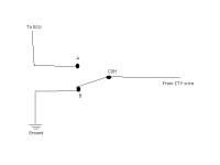
So...A SPDT switch would work. Put the COM on the "lights--CTY" side, and B terminal to ground and the A terminal to the side going to the ECU (see crude diagram). The easiest test area would be for you to drop either your map light or rear room light and try grounding the CTY wire; the ignition wire can't be grounded. Problem solved, go have a beer!:beer:
 

Attachments

  • Switch.jpg
    Switch.jpg
    11.7 KB · Views: 732
That's what I'm talkin about. Wow- thanks for taking the time to do that- much appreciated! I've had my OH console out so much I could take it apart in the dark, so I'll try there. I'll post results, it may be a few days... Thanks again.
 
Wiring HELP- Adding lights to turn on / off as DOOR opens

hello all - i think i'm somewhat on the right thread, but here's what i'm looking at doing - i want to add some running boards with lights on them. I'm in the VERY early stages, but i want to see if it is possible to have these lights come on when and if ANY door is opened, of course shutting off as the door is closed?
I'm not sure if the only way would be tieing into the dome light...or maybe even the puddle light on the review mirror.
please help and if you can provider documents, pics, or additional details it woudl be GREATLY appreciated.
Thanks!
Mike
 
hello all - i think i'm somewhat on the right thread, but here's what i'm looking at doing - i want to add some running boards with lights on them. I'm in the VERY early stages, but i want to see if it is possible to have these lights come on when and if ANY door is opened, of course shutting off as the door is closed?
I'm not sure if the only way would be tieing into the dome light...or maybe even the puddle light on the review mirror.
please help and if you can provider documents, pics, or additional details it woudl be GREATLY appreciated.
Thanks!
Mike

You can find the link to the factory service manual and wiring diagrams right here:

http://www.toyota-4runner.org/5th-gen-t4rs/65237-tis-fsm-2010-4runner-here.html

It's actually in the signature of Nashman whom posted directly above you, and was kind enough to host this for all of us :)


As far as tying in to either the puddle lights or the dome lights, both sound like feasible options. If you want to go with the puddle lights option, here's a thread that might be helpful to you:

http://www.toyota-4runner.org/5th-gen-t4rs/143034-wire.html#post1391651
 
Cut the Red Wire

That's funny- I actually had it narrowed down to the red and the green wires originally...but was leaning towards red.

24 years, and I still have all my fingers. Words to live by "Always cut the red wire..."
 

Members online

Forum statistics

Threads
278,304
Messages
3,554,041
Members
248,016
Latest member
Advally Service

Trending content

Back
Top