First steps into the mod world!

rubbman

New member
So I was sent home from work( my poison oak covered body scared people) so without a mechanic present( I usually pay a mechanic buddy to hang out incase I mess up) I started working on my 4runner. In a few hours I was able to change out my swaybar links, do the deckplate mod, and install some auxillary driving lights. I was pretty stoked on the outcome (considering my usual incompetence) but I do have a slight problem, I used a toyota factory switch and everytime I turn the switch on the fuse pops??? Does anyone have a wire diagram for a toyota auxillary light switch?
 
Register to hide this ad
I will probably repeat this I don't know how many times, but everyone LOVES pictures. So don't make this thread fail, show some pics. And what did you hook the lights up to?
 
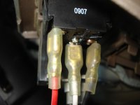
rear of switch
 

Attachments

  • rear 2.jpg
    rear 2.jpg
    77.6 KB · Views: 591
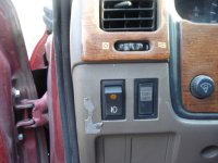
in the photo above orientation is 90 degrees clockwise, I do not now if I have it wired right.
 

Attachments

  • front 2.jpg
    front 2.jpg
    128.7 KB · Views: 631
The blade behind the light on the switch is where the ground goes. The middle blade is for the input and the bottom for the output.
 
J.A. said:
The blade behind the light on the switch is where the ground goes. The middle blade is for the input and the bottom for the output.
THANK YOU It worked will post pics later!
 
Cool, glad it worked. Just curious though...you are sending the 12+ output to a 30A relay (letting the relay handle the load) and not directly to the lights themselves, correct?
 
rubbman said:
THANK YOU It worked will post pics later!
NO I installed as is,battery to 15amp fuse to switch then directly to lights! I am not to savvy on the proper tecniques, any recomendations?? Diagrams? thanxs for the assistance.
 
For Aux Lights you need to use a relay.

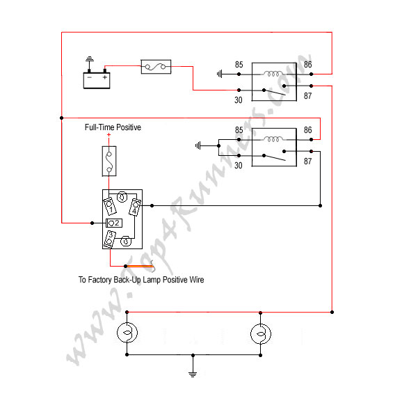
Referring to the diagram below. Your 12V+ switch output goes to pin # 86 on the relay rather than straight to the lamps. Put a wire on 85 and hook it to ground. That is your coil and when energized Pins 30 and 87 will have continuity. So wire one to 12V+ (fused) and the other is your output to the lamps. It may work how you have it now but the wires/switch can become very hot and cause a fire potentially.


relaytextA.gif
 
i need to put a relay in mine, i have mine running the same way yours are right now, and when i was out driving at night for 2 hours with my lights on i went to turn them off and it was really hot, i was nervice about a fire so i turned them off, yes u need to put a relay in, if anyone else has any wire diagrams on how i would like some help! and where do i get the relay? oreliys?


J.A., can you give me more info on what the relay connections go to, i only understood the common, (for ground ofcorse). but what goes n/o, n/c and coil mean?
 
Last edited:
shootmymime said:
i need to put a relay in mine, i have mine running the same way yours are right now, and when i was out driving at night for 2 hours with my lights on i went to turn them off and it was really hot, i was nervice about a fire so i turned them off, yes u need to put a relay in, if anyone else has any wire diagrams on how i would like some help! and where do i get the relay? oreliys?


J.A., can you give me more info on what the relay connections go to, i only understood the common, (for ground ofcorse). but what goes n/o, n/c and coil mean?

Sure, n/o and n/c stand for normally open and normally closed. You dont necessarily need a 5 pin relay with pin # 87a, that is not used in this application. You can buy a 4 pin relay if you see on, or the 5 pin whatever you find. Either is only around $5.

normally open means that when the relay is at rest (coil not energized by the switches 12v+ power) pins 87 and 30 are not connected. normally closed means that at rest 30 and 87a are connected together internally.

The coils is just that...a coil of wire around a piece of metal I believe that when 12v positve and negative are connected to it, energizing the coil, it magnatizes and draws an internal switch to connect pins 87 and 30 together.

12V positive is currently coming into your switch. When you turn the switch on, you send 12V+ out of the switch. Connect that to one side of the coil on the relay, the other side of the coil on the relay goes to ground. When you turn the switch on 12V+ goes from the switch and energizes the relays coil thereby magnetically connecting pins 87 and 30. If one side (either 87 or 30) is connected to 12V+ such as your battery via an appropriatly sized fused wire (perhaps 14awg or thicker with a 15amp fuse) it will send this power out the other side. That side goes out to your lamps.

Relays can be wired all kinds of ways but for your application this will work perfectly.

Any decent set of lamps comes with instructions and a relay and people really need to use it. I understand you may not have them so feel free to ask further questions if that is still not clear.
 
Last edited:
Well it looks like I will be buying 2 relays because I plan to add in a backup assistance light as well! Once again THIS FORUM RULES!!! You all have been a Sweet source of info (and amusement).
 
rubbman said:
Well it looks like I will be buying 2 relays because I plan to add in a backup assistance light as well! Once again THIS FORUM RULES!!! You all have been a Sweet source of info (and amusement).

Now that is a mod I have actually already planned out and have a full schematic drawn up for. Take a look below. Three way switch SPDT on-off-on that will activate the Aux reverse lamps automatically when put in reverse (switch in down position) and "on demand" when the switch is in the up position.

reverse_lamps.jpg
 
Does toyota have a swithc that would work with your design? Does the "full time positive" go back to the battery?
 
Last edited:
rubbman said:
Does toyota have a swithc that would work with your design? Does the "full time positive" go back to the battery?

Yes, so that they work when the vehicle is off such as when setting up camp, etc. You could also run it to a source that is 12V+ only when the ignition is on, and use that mode as a "back off" light for tailgaters on the highway.

No Toyota does not make a 3-way switch as per the above. You can go direct to one of their suppliers, Cole Hersee and buy 58328-103-BP which fits the 3rd gen switch cutout perfectly. It is a very nice switch, approx $15 at any local marine shop (its weather resistant) and some automotive supply stores.

B26c%2058328-103.gif
 
Because I am an idiot

once again I come groveiling for more info on wireing, I installed a relay and my light do not work, all messed up, so here is what I did. Red wite going from battery to switch now goes to into 30, out87 to switch. white wire goes from switch to lights. then black wire from lights to 85 then from 86 to ground. HELP?!?!?!?
 
Re: Because I am an idiot

rubbman said:
once again I come groveiling for more info on wireing, I installed a relay and my light do not work, all messed up, so here is what I did. Red wite going from battery to switch now goes to into 30, out87 to switch. white wire goes from switch to lights. then black wire from lights to 85 then from 86 to ground. HELP?!?!?!?
P.S. is there a way to wire the lights so they will be completely independant? I want to be able to flip the switch and go. no ignition. no parking lamps, just the lights.
 
Re: Because I am an idiot

rubbman said:
once again I come groveiling for more info on wireing, I installed a relay and my light do not work, all messed up, so here is what I did. Red wite going from battery to switch now goes to into 30, out87 to switch. white wire goes from switch to lights. then black wire from lights to 85 then from 86 to ground. HELP?!?!?!?

I am sorry, but it can t be explained any more clearly than the handmade diagram I posted. Why did you put 87 out to the switch? :( 86 goes to the switch.
 

Members online

No members online now.

Forum statistics

Threads
278,304
Messages
3,554,041
Members
248,016
Latest member
Advally Service

Trending content

Back
Top