I found "The One", 2001 Sport Ed. TRD SC'd

Well, I got it all done late last night. Everything fired up flawlessly and I'm getting better, more stable voltage readings at idle. I need to take it for a drive and see how it does, and test the winch again to see if this has relieved the stress it was putting on the electrical system. I took alot of pics, so I'll throw those up w/some more info when I get a chance.


Yeah, but the 4runner needed it too...

Your write-ups are so thorough! Great work BigFish!

X2 :thumb3:

:thanks:

What brand wire is that? Didn't feel like going with 1/0?

The wire is made by Scosche. It came out of an amp wiring kit that I've had collecting dust in a box in my garage for years. When I cut it open it had plenty of strands, and it was an honest 4 AWG size. I'm not using it for audio here, so I'm not concerned with it's ability to carry a quality signal, but rather it's ability to carry current. I'm sure it will work just fine.

Regarding my choice to go with 4 gauge vs. 1/0... Take a look at the table on this link>> Recommended Power and Ground Cable Sizes & Speaker Wire Size and Length

I picked the size of the cables based on the current I needed to carry. I'm not running a big stereo system, and I did this upgrade to help the electrical system deal with the amperage draw from the winch. The alternators on these things put out around 80A if I remember right, so I don't need a 1/0 cable with a 350A capacity. 4 gauge cable can handle 150A, which is more than sufficient for my application.

I actually reduced the capacity of the new charge wire even futher by using a 120A circuit breaker (same level at which the stock alternator charge wire is fused). The winch can pull alot of power, up to 410A, and I don't want the winch trying to pull that much current off the alternator. My main goal was to give it another path so it doesn't draw so much through the fuse box/fusible link.

Again, I already had the 4 gauge, so why not use it. Not to mention, 1/0 cable is big stuff, and I barely had the room to run the 4 gauge and still be able to get the battery back in.
 
WOW... I feel that much more informed with all the knowledge on this thread... and a bit of jealousy has formed too. Ride looks great! :bigok:
 
Last edited:
The Big 3… Continued

I spent a few afternoons last week finishing up the Big 3 upgrade and getting the battery installed. Everything went pretty smoothly.

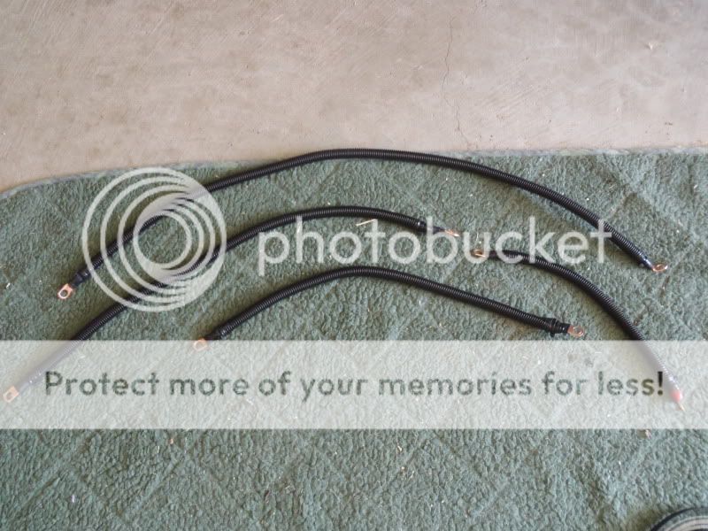
After I got the wires cut to length, and terminals soldered on and crimped, I took the time to add some extra insulation and protection against abrasion. Shorts on these wires = fires, and I don’t like fires in my engine bay.

86b3bf42.jpg~original


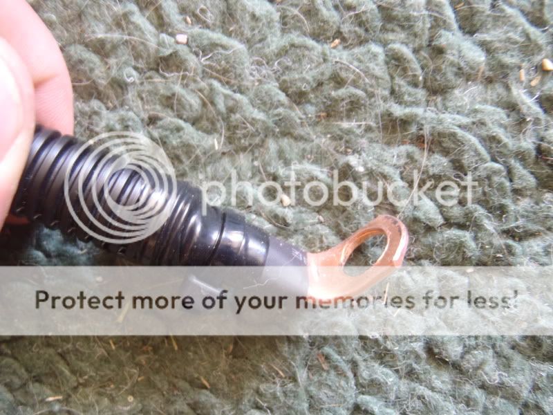
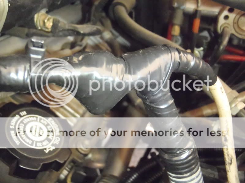
This is a close up of the engine side of the new engine to chassis ground. I had to bend the end of the terminal to accommodate the mounting location on the alternator bracket. You can also see the insulation… heat shrink tubing from wire to terminal, wiring loom over that, electrical tape over that, and then a zip tie around the electrical tape to prevent it from un-wrapping due to the heat in the engine bay.

591c73f4.jpg~original


Time to get down to business, but beforehand I took a few shots of the existing setup…

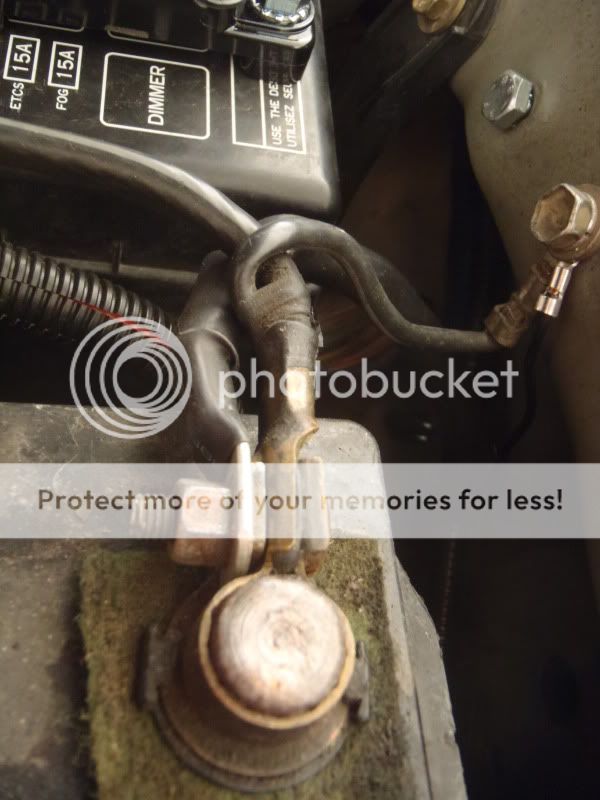
WEAK, weak, WEAK battery to chassis ground… this is probably the weakest link of the stock wiring.

9f8d1389.jpg~original


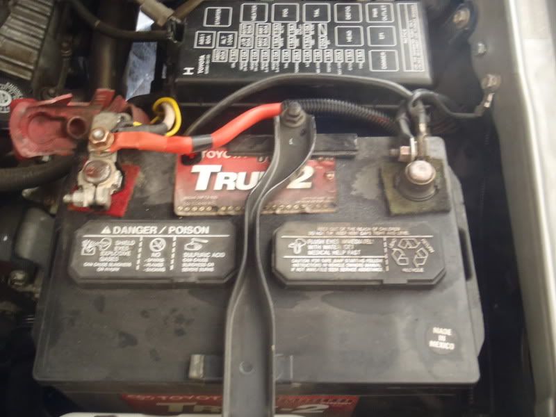
Positive terminal… Wires attached are Alternator charge wire > Batt…… Alt > Fuse Box > Fusible Link > Batt…. Winch Positive Terminal > Batt….. and IPF Lighting Positive > Batt.

b220e066.jpg~original


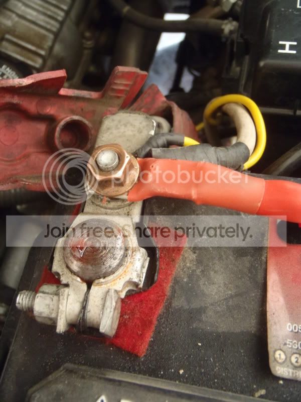
The whole shebang…. A leaky battery = one of my engine bay pet peeves!

253e230f.jpg~original


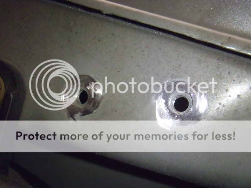
I took the paint off the inner fender @ the ground locations for a better ground connection. I ended up using the stock ground location, and another unused bolt hole located about 2 inches rearward.

e2895a38.jpg~original


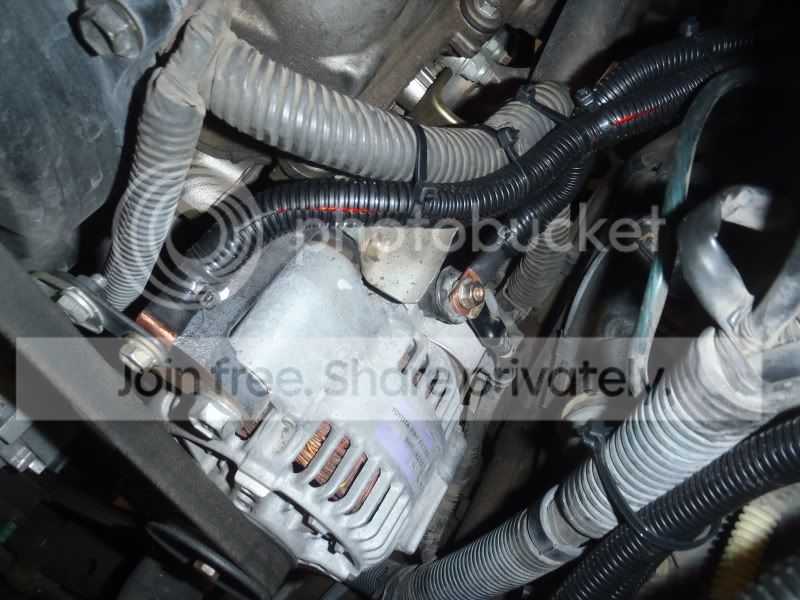
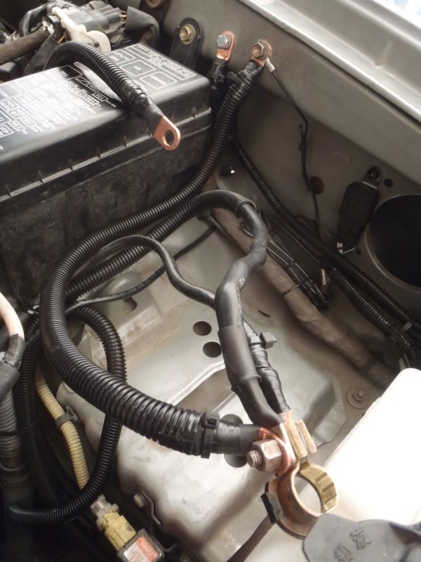
I then hooked up 2 of the Big 3 wires at the alternator side. The Engine to Chassis ground can be connected anywhere on the engine block to anywhere on the chassis. Since the alternator case is the ultimate grounding point of the entire electrical system, I decided to hook up right to the mounting bracket where I would be electrically closest to the alternator case.

The second connection was at the (+) Charging Post on the alternator. You can see the connection to the alternator mounting bracket at left (notice the bent terminal, which I had to do to keep the wiring out of the path of the alternator drive belt), and the connection to the alternator charging post at center…

08b27c29.jpg~original


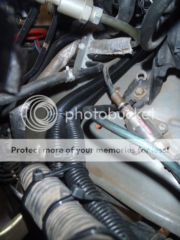
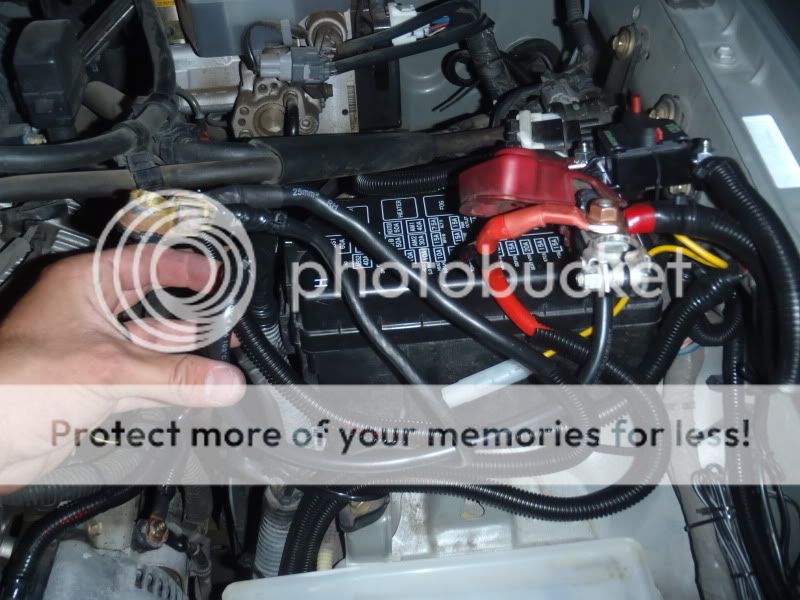
The new wires follow the existing wiring rearward, then separate off toward the driver’s side behind the fuse box….

9ae66fd2.jpg~original


The third wire of the big 3 is the Battery (-) to Chassis wire… I connected one side to the negative terminal and the other side to the stock grounding point on the inner fender. In this shot you can see the Battery (-) to chassis wire in the foreground, the Alternator Case (Engine) to Chassis wire connected to the inner fender just behind it, and the new Alternator Charging Post to Batt (+) wire draped over the fuse box.

5793362a.jpg~original


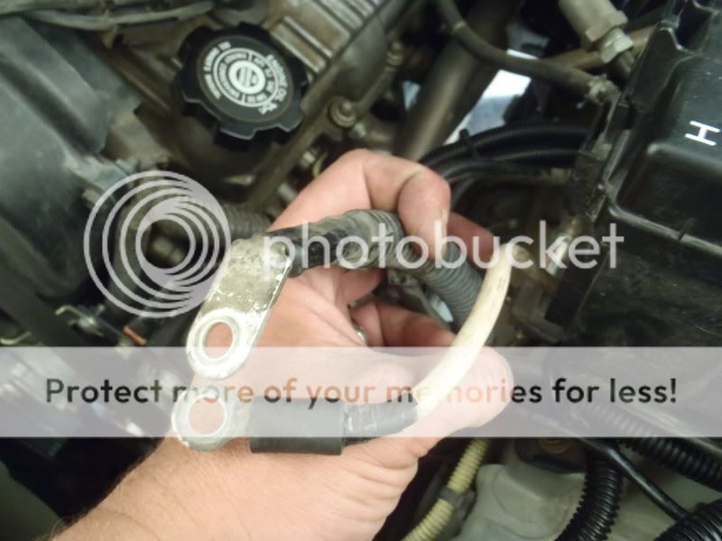
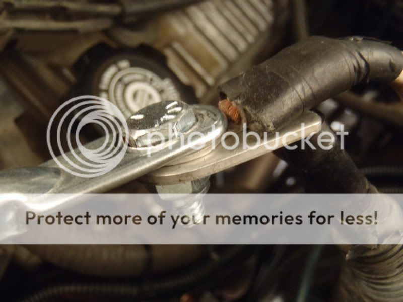
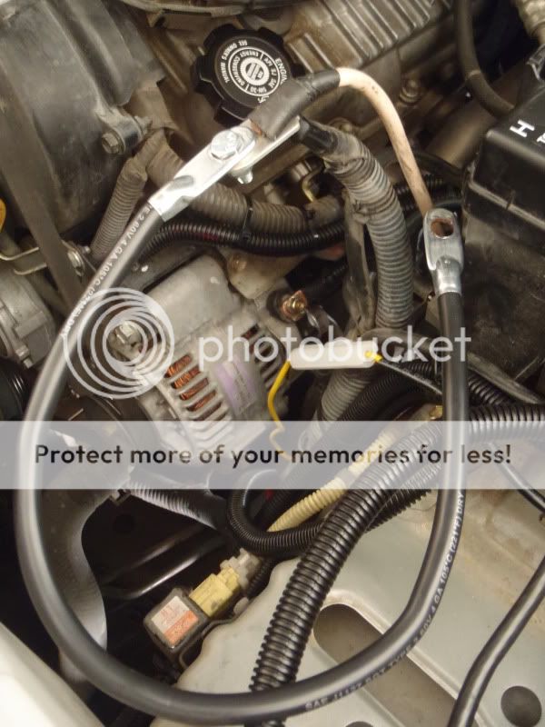
Now to deal with extending the stock wiring on the (+) side of things. The two wires that need to be extended are the stock Alternator to Batt (+) wire, and the fusible link coming from the fuse box. The simplest way to do this is like so:

30954b5d.jpg~original


fb1dcf96.jpg~original


dbf25ef0.jpg~original


The extension wire is 19 inches long, 4gauge and should have plenty of current carrying capacity to serve as a jumper from the existing wires to the Battery (+) terminal. The bolt and lock nut make sure that there is a strong connection that won’t come loose over time. Finally, I made sure to insulate the hell out of it. I took the entire junction and wrapped it in high quality electrical tape, wrapped that in thick plastic sheet, wrapped with more electrical tape, and repeated one more time. Adding the plastic sheet makes sure the bolt won’t eventually wear through the electrical tape and ground out… again, NO FIRES!

48f3ecde.jpg~original


I then had enough length on all the (+) cables to make the connection to the terminal and prepare to drop in the battery.

14795858.jpg~original


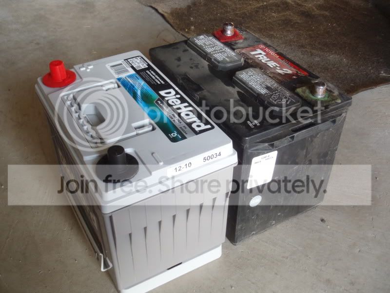
New VS. Old… Again, with the spacer, you can see that the group 34 battery is nearly identical in size to the group 24….(Also, note the reversed terminals)

ff48af25.jpg~original


I ended up hacking off the old (-) battery terminal, soldering on a new copper ring terminal, and using a completely new brass battery terminal on the negative side. I felt it was much cleaner, stronger, and provided a better connection than the stock (-) terminal, which is very flimsy.

4c19e875.jpg~original


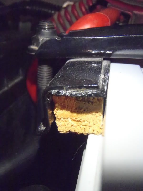
The only thing you have to do to get the stock battery hold down to work on the Die Hard group 34 is cut a small piece of wood, about 3 inches long, by 5/8” square to fill a small gap that is created between the tie down and the rear side of the battery.

d1158454.jpg~original


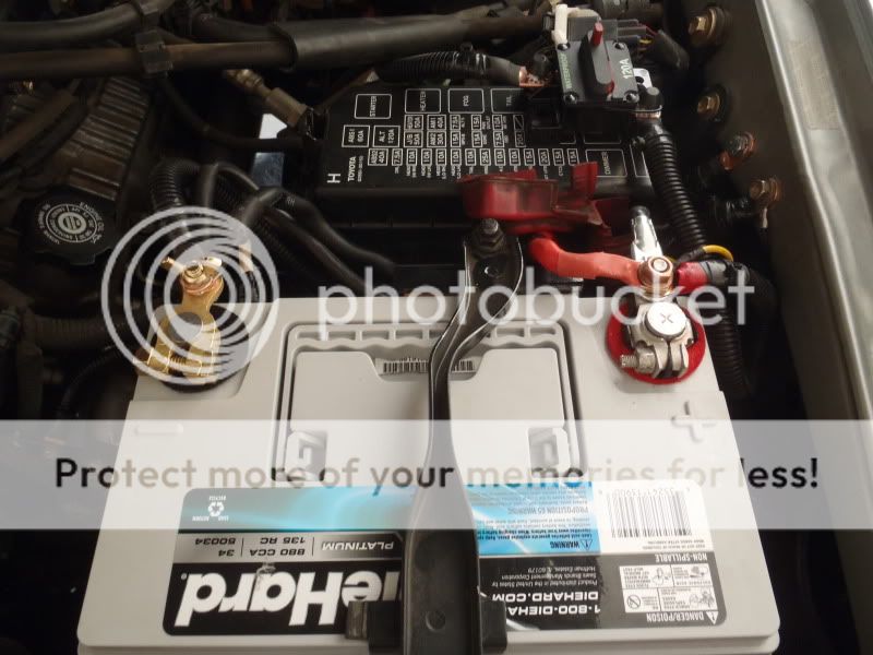
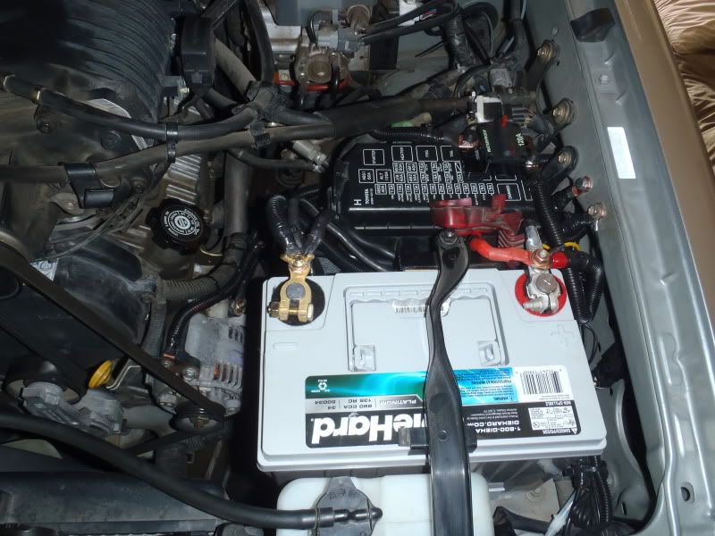
Finally, the overall shot of the finished product. You can also see the new 120A circuit breaker I added inline on the new Alternator Charging Post to Battery (+) wire. I used Velcro tape to mount the breaker to the top of the fuse box cover, where it can be easily accessed in case it trips, or for troubleshooting.
661348b7.jpg~original


Overall, it was a pretty clean install using the group 34. I have noticed a dramatic increase in idle voltage, which came up from 11.8V to 13.3V. It seems to have smoothed out the idle a little bit, and has definitely been noticeable at night, where the lighting remains at a constant brightness. Before the upgrade, my lighting would dim SIGNIFICANTLY at stoplights or when the truck was idling. I tested the winch on the upgraded electrical system, and it is MUCH HAPPIER. On the old setup, when I activated the winch, the dash lights would flicker a bit and the alternator warning light (red battery symbol) would come on. The Scangauge showed the voltage dropping to almost 11V when the winch was on with the old setup, and with the new setup it does not go below 12.5V. Also, the truck starts much easier with all those cranking amps. For $300, I am VERY happy with this upgrade.

 
Last edited:
BigFish, your write ups are extremely detailed and the install looks PRO all the way.

I currently have the optima red top and the stock alternator with 200k miles. I am kind of impressed that my alternator is still going.

Did you upgrade all power cables because you have a high current aftermarket alternator and it was necessary?

In your opinion, how much of the difference is the battery and how much is the new cables?
 
I'm still running the stock alternator. If I run into issues at this point, I'll have to install a CS-144, but we'll see on that one.

The electrical system is like a water system on a house that runs off a well.

The alternator = your well pump, it is the source

The battery = your pressure tank, it stores the water and maintains pressure for a constant flow, provides a reserve for large, immediate demands.

The wiring = your pipes... the bigger the pipes, the more flow, up to the capacity of the pump.

So basically, I improved 2 of the 3. The reason I didn't do the alternator is because I don't have a large CONSTANT drains... only large TEMPORARY drains (i.e. winch, IPF's). The only problem I may run into is that if I draw down the battery too much, the alternator may have a hard time re-charging it. Considering the amount of winching I plan on doing I don't think I'll run into that problem, but if I do, the CS-144 is only a $150 upgrade, and they actually sell an adapter harness for the upgrade so you don't have to hack up your stock alternator wiring harness (Link to adapter harness > http://store.alternatorparts.com/wi...cs-style-plug-to-toyotal-oval-style-plug.aspx).

As far as the difference goes, I'd say 90% is the battery, and 10% is the new cables.
 
Last edited:
Cool project man, a lot of people on this forum could really take some notes on your electrical installations, your stuff is clean!


Just a thought, you should add a sort of "Chapter" guide in your first post like Liny4Runner has done on his build thread. There is so much information in this thread that is getting buried in the pages.

I saw on the previous page you were saying that Jaos skid was just for looks... If you ever decide to upgrade, I will buy it.
 
Hey BigFish...your efforts are well appreciated, sharing valuable info with photos upon photos paired with detailed explanation just makes the life of the next modder a lot easier..How can I commend you for a 6 star?
 
Cool project man, a lot of people on this forum could really take some notes on your electrical installations, your stuff is clean!

Just a thought, you should add a sort of "Chapter" guide in your first post like Liny4Runner has done on his build thread. There is so much information in this thread that is getting buried in the pages.

I saw on the previous page you were saying that Jaos skid was just for looks... If you ever decide to upgrade, I will buy it.

That's a big compliment man, thank you! When I'm doing electrical work, my goal is always to make it look like it rolled off the assembly line with that wiring intact.

I saw that on Liny's thread, and I think COB has done the same thing. I thought to myself "That's a great idea!" but I resisted doing it because I didn't want to come off as a copycat. A good idea is a good idea though, and I think you're right.

RE the JAOS skid, you will be the first person I contact if I decide to upgrade. I've been considering a budbuilt for a LONG time.

x2 on that Wilson.

Great work man. Your work is always so clean!

Thanks amigo... We need to get these two out on a trail again soon. Now that I've got the winch running we can really get into some trouble.

Hey BigFish...your efforts are well appreciated, sharing valuable info with photos upon photos paired with detailed explanation just makes the life of the next modder a lot easier..How can I commend you for a 6 star?

Photos upon photos is right... sometimes I think I include too many. Your commendation right here is enough man. Thank you very much. Everything I go into detail with in this thread is stuff that I myself have not been able to find much information on. When I put the posts together I just try to add the info that I was looking for when I set out to do the mods.
 
In-Cab Winch Control

I’m going to do a post on this too, since it might help someone down the road with an idea or two on how to do this. When it came time to wire up my winch control box, I had a few things I wanted to accomplish:

1. I did not want the control box mounted on top of the ARB, this was mainly due to aesthetics… I don’t like the look of the box mounted on the bumper between the lights, and I would have had to fabricate a bracket to mount it there.

2. I wanted to be able to control the winch from inside the cab, WITHOUT having the cord for the winch controller running across my hood and in the driver’s side window.

3. I wanted to be able to run the winch from inside the vehicle, with the windows up, in case of bad weather, or from outside of the vehicle.

4. I didn’t want to mount the control box in the engine bay because of heat/access issues.

Here’s what I did:

First, I stripped down the control box to see what I was working with. Once you get it apart, it’s pretty simple. You have your solenoid, a wiring harness that connects it to the plug for the controller, and the box itself (which I might mention isn’t anywhere close to sealed, waterproof, even weatherproof).

b78155b5.jpg~original


My solution was to find a way to mount the plug for the controller inside the cab of the vehicle. In order to do that, all I had to do was extend this harness:

a5911012.jpg~original


I simply added some 15 foot lengths of 14 gauge wiring using spade terminals. I made sure to solder the wire into the spade terminals for a secure connection, then insulated the splice with heat shrink tubing. I would have just soldered wire to wire, but I didn’t want to cut off the spade terminals on the existing Smittybuilt harness. Throughout the entire installation, I did not modify the Smittybuilt wiring in any way, mainly so that they won’t question me in the event that I need to have anything warrantied for a defect.

5a6485c7.jpg~original


Once I figured that out, I had to figure out a place to mount the solenoid. I wanted to work with what I had, so I took a look at the mounting bracket that came with the ARB, and started sniffing out a spot to mount the solenoid. Once I found the spot, I had to modify the ARB bracket to fit the bolt pattern on the Smittybuilt solenoid. It just took a little drilling.

5f5f4488.jpg~original


Next, I took a few minutes to make sure all the connections at the solenoid were nice and snug. After that, I did my best to make the solenoid water and weather resistant. I used some thick plastic sheeting to wrap the solenoid as a base layer, then used electrical tape to basically seal the solenoid inside the plastic.

03b6bb4f.jpg~original


83af93d7.jpg~original


The mounting location I went with is a spot that is up behind the bumper on the passenger side. There is a little corner where the solenoid and ARB bracket fit perfectly.

0eb6f791.jpg~original


I fabricated a bracket using the metal straps that came with my B&M transmission cooler. The bracket provides mounting point for the second bolt hole on the ARB bracket and keeps the solenoid level and well supported.

e52aa28f.jpg~original


After I got the solenoid mounted, I found some routes for the power wires….

01c9cbca.jpg~original


6323ec2c.jpg~original


Then pulled them out, put some wiring loom on them to protect against chafing/grounding, and re-installed.

bf7bfcd1.jpg~original


Then I ran the wiring for the harness extension. Starting just underneath the horn on the passenger side, where the solenoid is mounted….

caa7e7cf.jpg~original


Along the A/C lines….

960be84e.jpg~original


Under the headlight and along the inner fender…

c29170ec.jpg~original


Through the firewall on the driver’s side…. BTW, that blue amplifier wiring on the left is NOT connected to the battery, and is an example of an unsafe wiring run. The way that wire is pressed up against the sharp edge of the firewall is asking for trouble. I don't know why the previous owner didnt just go through the grommet.

fc1d3239.jpg~original


Under the carpet to the transmission tunnel…. Where I used my Dremel to cut a hole for the plug, ran the wiring through, and soldered the wires to the terminals on the plug. I made sure to insulate them heavily, because if either of the (+) wires touches the ground, the winch will activate whether the ignition is on or not. If they somehow grounded out that could be very bad.

e069473e.jpg~original


Harness all finished…

45585813.jpg~original


Bada bing…

2fb50877.jpg~original


Bada boom…

e036a1cd.jpg~original


Mission accomplished. While I was at it, I took a quick second and Plasti-Dipped the ARB emblem on the bumper for an all black look.

90f3ec0b.jpg~original


Now, when it’s time to do some winching, all I have to do is plug in the controller right there in the cab and go to town. If I need to winch from outside of the cab, I still have the 12 foot cable on the controller, so I have that functionality. And ultimately, if I decide to add a permanent switch in the cab I can do that by simply running some extensions off the existing wires up to a momentary switch, while retaining the plug as well. And, if something craps out, I can pull all the components, put them back together exactly the way they came from Smittybuilt, and send them in for warranty.
 
I know you've heard it before man....but AWESOME WRITE-UPS! You are a real perfectionist with your mods, and it really shows!
 
Said it before, I'll say it again and I'm sure I'll be saying it plenty in the future. Great mods backed up by great write-ups. You follow your clean and thorough mods with the same attention to detail on your write-ups. Makes it a pleasure to flip through them.
 
I know you've heard it before man....but AWESOME WRITE-UPS! You are a real perfectionist with your mods, and it really shows!

Awesome write ups. Thanks for taking the time to put these together.

Said it before, I'll say it again and I'm sure I'll be saying it plenty in the future. Great mods backed up by great write-ups. You follow your clean and thorough mods with the same attention to detail on your write-ups. Makes it a pleasure to flip through them.

Thanks for the kind words gentlemen! Alot of the reason I'm documenting everything so heavily is so that I can remember what I did. I swear I've got the memory of an 80 year old man. Eventually, when I get this thing finished I intend to print this entire thread and keep it in the file for the truck as a log of the build.

Hepar... Sliders?

Those are some great write-ups and all, but I forget, what does your truck look like again... :)

It's rather plain, actually. :lmao: I know what you mean though, I need to actually get this thing out in the wild now and then. I'm coming up fast on one year since I bought it and I'd like to have it more or less done by then.

The only major thing left on my "To-Do" List is the URD Kit and the 2.2" Pulley, and tuning, so I'll be tearing into that job here pretty soon.
 
It's rather plain, actually. :lmao: I know what you mean though, I need to actually get this thing out in the wild now and then. I'm coming up fast on one year since I bought it and I'd like to have it more or less done by then.

The only major thing left on my "To-Do" List is the URD Kit and the 2.2" Pulley, and tuning, so I'll be tearing into that job here pretty soon.

Love your truck brotha, and especially love your write-ups, just joshing you a little cause i'm dying to see some new "action" pics :D
 

Members online

No members online now.

Forum statistics

Threads
278,316
Messages
3,554,120
Members
248,016
Latest member
Advally Service

Trending content

Back
Top