
Photovogel
New member
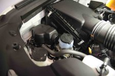
I just picked up my new 2013 4Runner and was ready install a dual battery system. When I opened up the hood I ran into an unexpected surprise. I was planning to install the battery in the “traditional” location at the front of the engine compartment on the passenger side, just behind the head light. When I had looked at the 2012 4Runners this spot was largely open – you just needed to relocate the power steering reservoir. However on the new 4Runners they have placed some complicated looking stuff in the “free” space! I don’t know exactly what it is, but it has a small coolant hose which runs to the engine block, plus a whole bunch of other connections. See photo 1.
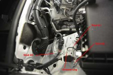
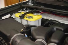
Therefore I had to move to Plan B – still locating the battery on the passenger side, but up close to the firewall. You will notice that there are some wiring connectors in this space, but they are all down tight against the wheel well. You will also see that there are THREE studs available for potential use as mounting points for the battery tray. In addition there is a major grounding lug already in place, needed to serve as a ground for the new battery. No surprise these three studs are METRIC and I’ve found they are size 8 with a 1.25 thread pitch. (note there are TWO thread pitchs for size 8 – you want the 1.25). See photo 2.
So the basic plan is to use these studs as the three point foundation for the battery tray. The foundation is built using Coupler Nuts, Threaded Rod, and Regular Nuts. By assembling these in a combination of lengths you get a nice three point base onto which to bolt the battery tray.
Here’s a basic run down of my materials:
Optima Yellow Top Group 34 Battery – 650 AmpHour capacity (Note if you buy this from Amazon you won’t get the 3 year manufacturer warranty – so pay more and buy thru an approved distributor)
Battery Tray – Dorman 111751 Champ Battery Tray ($16.97) @ Amazon
Battery Hold Down – Westward 1EFZ6 Battery Hold Down, 8 Inch ($5.45) @ Amazon
Metric Hardware: Qty of 8 Coupler Nuts; Qty of 6 Washers; Qty of 4 Regular Nuts; Qty of 3 Bolts; One piece of All Thread. Size of all the above is Metric #8 with a 1.25 thread pitch. This hardware is difficult to find – regular hardware stores don’t carry these metric items, auto shops don’t have it either. I finally got what I needed at a local Fastenal store – these guys are nationwide and are really very helpful!
I used Loctite Blue Thread Locker to coat all the threaded parts and to keep them from loosening up later on.
Battery Cable – for runs typical in a 4Runner you need #4 Gauge Wire – a length of 10 feet was all I needed to hook everything up.
While not strictly related to the battery installation itself, you WILL need some sort of a relay to connect and disconnect your two batteries. I used IBS-DBR 12V, which is a neat little relay offered by Intelligent Battery System in Switzerland. Their US Distributor is Extreme Outback Products (Welcome to our Website : Extreme Outback) and phone 866-447-7711. You won’t find better people to work with than these guys.
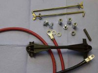
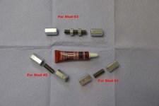
Step 1 Cut and fit the All Thread and Couple Nuts to build your base. See photo 5. The picture will give you an idea of about what lengths of All Thread you need to cut. When you get into this you will see that Stud #3 is lower(shorter) than the other two studs, therefore it will need a longer extension to make your battery tray level. For Studs #1 & #2 you start with a Regular Nut at the bottom, then a Coupler Nut tightened down on top of that to “lock” these two nuts onto the Stud. Then you follow with a short section of All Thread screwed about half way into the Coupler Nut. Finally you screw another Coupler nut down onto the remaining All Thread until it can be tightened against the first Coupler Nut. For Stud #3 you need a longer extension, so the piece of All Thread is longer. I suggest you use 2 Regular Nuts in between the two Coupler Nuts to tighten(jam) the Coupler Nuts onto the All Thread (see photo). You don’t want this stuff vibrating loose. At this point don’t final assemble them, just get them loosely assembled on the three Studs. Check for level among the three assemblies – so that your tray will be level when it’s mounted.
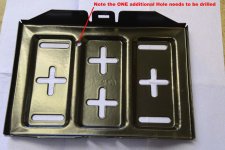
Step 2 Set the Battery Tray on top these assemblies and figure out where you need to drill any extra holds in the tray for mounting. I actually cheated and just used a piece of cardboard, same size as the tray, used some “white out” (you know, that stuff you used to use to cover over typing errors on paper) to spot the tops of the assemblies. When I positioned to card board over the assemblies and pushed down, the white out was transferred to the cardboard and now I have a drilling template. Drill the hole(s) as needed in your battery tray. See photo 4
Step 3 Now you are ready to “permanently” mount the hardware onto the three Studs. For Studs #1 & #2, tighten a Regular Nut down tight onto the base of the Stud. Then use your Locktite Blue on the threads and mount the first Coupler Nut down, tightening it well against the Regular Nut. Then install the short piece of All Thread down into the first Coupler Nut using Locktite. Finally mount the second Coupler Nut down onto the first one using Locktite. For Stud #3 there is already a factory nut in place, so mount your first Coupler Nut right on top of it using Locktite. Assemble the balance of the hardware using Locktite and using the Regular Nuts to “jam” into the Coupler Nuts, locking them properly onto the All Thread.
Step 4 Next mount your Ground Battery Cable onto the vehicle grounding lug shown in the photo. DON’T FORGET THIS STEP !! You won’t be happy if you mount the battery tray and forget to do this first.
Step 5 Mount the Battery Tray onto your foundation using the Metric Bolts along with washers. Don’t forget to use the Locktite and torque down tightly.
Step 6 Place the Optima Yellow Top Battery onto the tray, position the terminals toward the firewall side.
Step 7 Cut the threaded battery holder rods to length and mount this to the tray and clamp the battery firmly in place.
Step 8 Connect the Ground Wire to the Negative terminal of the battery.
Now you are ready to connect your new battery to the relay – use the manufacturer’s instruction from this point on.
Therefore I had to move to Plan B – still locating the battery on the passenger side, but up close to the firewall. You will notice that there are some wiring connectors in this space, but they are all down tight against the wheel well. You will also see that there are THREE studs available for potential use as mounting points for the battery tray. In addition there is a major grounding lug already in place, needed to serve as a ground for the new battery. No surprise these three studs are METRIC and I’ve found they are size 8 with a 1.25 thread pitch. (note there are TWO thread pitchs for size 8 – you want the 1.25). See photo 2.
So the basic plan is to use these studs as the three point foundation for the battery tray. The foundation is built using Coupler Nuts, Threaded Rod, and Regular Nuts. By assembling these in a combination of lengths you get a nice three point base onto which to bolt the battery tray.
Here’s a basic run down of my materials:
Optima Yellow Top Group 34 Battery – 650 AmpHour capacity (Note if you buy this from Amazon you won’t get the 3 year manufacturer warranty – so pay more and buy thru an approved distributor)
Battery Tray – Dorman 111751 Champ Battery Tray ($16.97) @ Amazon
Battery Hold Down – Westward 1EFZ6 Battery Hold Down, 8 Inch ($5.45) @ Amazon
Metric Hardware: Qty of 8 Coupler Nuts; Qty of 6 Washers; Qty of 4 Regular Nuts; Qty of 3 Bolts; One piece of All Thread. Size of all the above is Metric #8 with a 1.25 thread pitch. This hardware is difficult to find – regular hardware stores don’t carry these metric items, auto shops don’t have it either. I finally got what I needed at a local Fastenal store – these guys are nationwide and are really very helpful!
I used Loctite Blue Thread Locker to coat all the threaded parts and to keep them from loosening up later on.
Battery Cable – for runs typical in a 4Runner you need #4 Gauge Wire – a length of 10 feet was all I needed to hook everything up.
While not strictly related to the battery installation itself, you WILL need some sort of a relay to connect and disconnect your two batteries. I used IBS-DBR 12V, which is a neat little relay offered by Intelligent Battery System in Switzerland. Their US Distributor is Extreme Outback Products (Welcome to our Website : Extreme Outback) and phone 866-447-7711. You won’t find better people to work with than these guys.
Step 1 Cut and fit the All Thread and Couple Nuts to build your base. See photo 5. The picture will give you an idea of about what lengths of All Thread you need to cut. When you get into this you will see that Stud #3 is lower(shorter) than the other two studs, therefore it will need a longer extension to make your battery tray level. For Studs #1 & #2 you start with a Regular Nut at the bottom, then a Coupler Nut tightened down on top of that to “lock” these two nuts onto the Stud. Then you follow with a short section of All Thread screwed about half way into the Coupler Nut. Finally you screw another Coupler nut down onto the remaining All Thread until it can be tightened against the first Coupler Nut. For Stud #3 you need a longer extension, so the piece of All Thread is longer. I suggest you use 2 Regular Nuts in between the two Coupler Nuts to tighten(jam) the Coupler Nuts onto the All Thread (see photo). You don’t want this stuff vibrating loose. At this point don’t final assemble them, just get them loosely assembled on the three Studs. Check for level among the three assemblies – so that your tray will be level when it’s mounted.
Step 2 Set the Battery Tray on top these assemblies and figure out where you need to drill any extra holds in the tray for mounting. I actually cheated and just used a piece of cardboard, same size as the tray, used some “white out” (you know, that stuff you used to use to cover over typing errors on paper) to spot the tops of the assemblies. When I positioned to card board over the assemblies and pushed down, the white out was transferred to the cardboard and now I have a drilling template. Drill the hole(s) as needed in your battery tray. See photo 4
Step 3 Now you are ready to “permanently” mount the hardware onto the three Studs. For Studs #1 & #2, tighten a Regular Nut down tight onto the base of the Stud. Then use your Locktite Blue on the threads and mount the first Coupler Nut down, tightening it well against the Regular Nut. Then install the short piece of All Thread down into the first Coupler Nut using Locktite. Finally mount the second Coupler Nut down onto the first one using Locktite. For Stud #3 there is already a factory nut in place, so mount your first Coupler Nut right on top of it using Locktite. Assemble the balance of the hardware using Locktite and using the Regular Nuts to “jam” into the Coupler Nuts, locking them properly onto the All Thread.
Step 4 Next mount your Ground Battery Cable onto the vehicle grounding lug shown in the photo. DON’T FORGET THIS STEP !! You won’t be happy if you mount the battery tray and forget to do this first.
Step 5 Mount the Battery Tray onto your foundation using the Metric Bolts along with washers. Don’t forget to use the Locktite and torque down tightly.
Step 6 Place the Optima Yellow Top Battery onto the tray, position the terminals toward the firewall side.
Step 7 Cut the threaded battery holder rods to length and mount this to the tray and clamp the battery firmly in place.
Step 8 Connect the Ground Wire to the Negative terminal of the battery.
Now you are ready to connect your new battery to the relay – use the manufacturer’s instruction from this point on.


 olice:............


