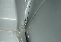
Intall Progress PICS

FlyingDutchMan

New member
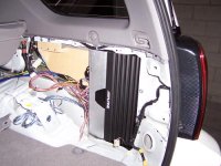
First let me thank Frank and Rando for their help in planning and the layout of this project.

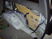
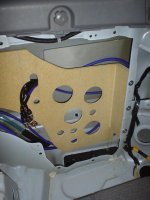
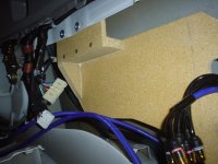
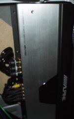
I have attached some pics of the progress so far.

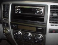
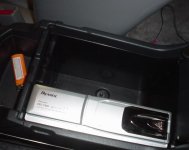
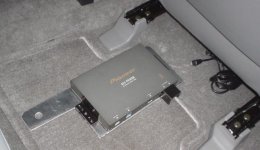
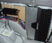
The components that are going in are a Alpine F450 5 Channel Amp for which I built the custom bracket. The Pioneer Premier 860 MP HU, SAT XM Reviever and 6 disc changer. We'll be re using the stock JBL door speakers. The stock sub is gone and will be replaced by a JL Audio ProWedge.

Let me know what you guys...
 

Attachments

  • amp rack.jpg
    amp rack.jpg
    57.3 KB · Views: 3,619
Register to hide this ad
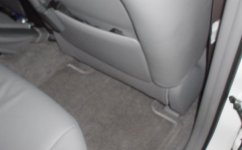
Pioneer 6 disc in the arm rest, it is daisy chained to the XM reciever which is connected to the HU with IP Bus cable, pretty slick set up on Pioneers parts.
 

Attachments

  • cd changer.jpg
    cd changer.jpg
    42 KB · Views: 3,519
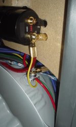
Yes, your right, I'll have to spend a little bit of time strapping everything down. I still need to mound a small .5 Farad cap, and build the ground wires. But the parts are still on the way with UPS.

ToyotaDoodz said:
VERY professional work on the custom bracket. Looks great so far. Can you use tie downs to keep the wires from touching the inside the body panel to avoid a future rattle?
 
Thanks...
There are two things I still need to do behind the HU.

One I need to attach the dimmer/illumination wire, but I am not sure which wire to plug it into on the factory harness. Do you know which on this is?

And second, correct me if I am wrong, I need to run a lead from 12v Switched and splice it into the fatory antenna amplifier on the the factory haness? CORRECT?

rando said:
...look'n good so far!
 
Unless I'm missing something, the wiring manual does not indicate that there is an illumination circuit running to ANY of the OEM head units -- I don't recall if my 6 speaker system ever lit up with the headlights or not. You can always check for an illumination wire with a meter. Look at the connector pin-outs below. Any wires that are on the unused pins are potential candidates for illumination. Otherwise, you'll need to tap into your lighting circuit elsewhere.

Yes, you need to power the antenna amplifier if you want to get reasonable reception. For my CarPC, I just tied the antenna amp to ACC. For the JBL system, the antenna amplifier lead is a black wire on pin 13 of the 20 pin connector R1. You can tell R1 from R5 (also 20 pins) by looking at the pin layout. R5 has a consistent pin spacing, R1 has consistent pin space except on the corner pins. The corner pin holes are larger.

Connector R1 - 20 pins
-------------------------------
01 Blue/Yellow BU+B Battery from 20A Radio No. 1 Fuse
02
03
04
05 Black TX+ Data Bus to Amplifier
06
07 White/Red MUTE signal to Amplifier
08 Black R+ (shielded) to Amplfier
09 Red R- (shielded) to Amplifier
10 Shield SGND for audio inputs to Amplifier
11 Gray +12V ACC+B through 7.5A ACC fuse
12
13 Black ANT+B Output
14
15 White TX- Data Bus to Amplifier
16
17
18 White L+ (shielded) to Amplifier
19 Green L- (shielded) to Amplifier
20 Brown GND

Connector R4 - 12 Pins
--------------------------------
01
02
03
04
05
06 Pink MUTE to rear audio controller
07
08
09 Red TX+ to rear audio controller
10 Green TX- to rear audio controller
11
12

Connector R5 - 20 pins
----------------------------------
01
02
03
04
05
06 White/Red GND to wheel controls
07 Violet/White SW1 to wheel controls
08 Yellow/Black SW2 to wheel controls
09
10
11
12
13
14 Shield SLD1 cable shield for audio connections to rear audio controller
15 Black RSR+ to rear audio controller
16 White RSR- to rear audio controller
17 Red RSL+ to rear audio controller
18 Green RSL- to rear audio controller
19 Violet RMU remote mute signal from rear audio controller
20

 
Found it, the wiring manual doesn't show the ILL leads in the radio circuit (strange) but they do show up in the illumination circuit. I guess I should only look at the OVERALL wiring schematics in the future, instead of the individual circuit wiring.

Here ya go.

R1
--------------------
02 Green ILL+
12 White/Green ILL-

R5
-------------
06 White/Red GND, GND for illumination circuit ???

ILL+ appears to come on with the tail lights. ILL- appears to be the variable illumination voltage controlled by the dash rheostat. I'd need to study this a bit more to be sure on what's what. Give the wiring manuals a look.
 
Rando-
You are so freaking money, that saved me so much time. Thanks agian

I figured the dash ILL wiring would be on another schematic, thanks for looking that up.

Since the Pioneer doesn't accept a rheostat dimmer, I might try the tail light pin. That might be a better option.

I'll scalen the pins with the Fluke meter and see what happens.


You CAN us the rheostat dimmer lead, but you have to keep the dimmer set to a certain setting for it to work properly and not make the Pioneer display flicker whne you turn on the lights.

Thats my two cents.
 
Here is a pic of the amp mounted. As you can see it barely fits. Don't worry I'll clean up the wiring as soon as the rest of the parts get here and complete the install.
 

Attachments

  • 1.jpg
    1.jpg
    34.2 KB · Views: 3,480
I think if you just use ILL+ and a normal GND and it'll give you the on/off illumination lead you need. ILL- looks like it's a path back to ground through the rheostat -- make sure to check it with your meter first.

The amp install looks nice!
 
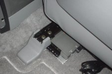
Here is a view of the completed XM install, you can't even see it under there and I didn't even have to drill any extra holes in the car...
 

Attachments

  • dsc01849.jpg
    dsc01849.jpg
    31 KB · Views: 1,668

Members online

Forum statistics

Threads
278,304
Messages
3,554,041
Members
248,016
Latest member
Advally Service

Trending content

Back
Top