JohnTx12's G5 Stage III Retrofit

JohnTx12

New member
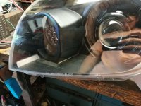
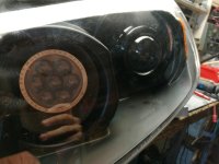
Like many people, I appreciate good headlights. Shortly after I purchased my 05 4Runner I started looking into doing a retrofit; something I had never done before. While I stretched the process over the course of three weeks (lots of part ordering and designing as I went) and many hours, I didn’t find anything particularly challenging. Hopefully, this guide will aid some people and give people some ideas. I primarily referenced (http://www.toyota-4runner.org/4th-gen-t4rs/183555-tins-mini-h1-retrofit.html) and then made up the rest as I went. I do apologize for any formatting or scattered images. This is my first guide I've ever tried to put together.

I recommend buying a second set of headlight housings, I feel like its relatively inexpensive and will give you the comfort of knowing you're not out a vehicle if you screw something up.

I bought and returned several items throughout the whole project but here is my final parts list:
Black 2003 2004 2005 Toyota 4Runner 4-Runner Headlights Headlamps Left+Right
G5 Stage III Parts Package
Bixenon Projectors:
G5-R LHD (3")
Compatible Ballasts/igniters:
Morimoto XB35 (35W)
D2S HID Bulbs:
D2S: XB 5500K
Shroud Style:
Apollo 3 Black Series
Wiring Harness: (match stock bulb size)
HD Relay: 9006/9005
Headlight Sealant
Gray: RetroRubber
LED Halos
110mm Pivot Switchback
High Beam: Profile HI-Lens LED
2 Pieces set 9005/9006 Headlight Bulb Xenon Halogen HID Light Connector Wire, Harness
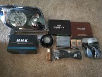
0-Parts picture.jpg

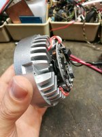
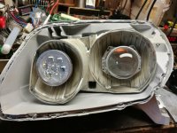
Per the recommendations from Lightwerkz.net I went with the larger G5-R projectors, reason being, our headlight housings are huge and have the room. For the high beam side I went with the Profile HI-Lens LEDs which also serve as DRLs (30% power on DRL, 100% for high beam) I did not use any shroud on the DRL/High beam because there is almost no room for one and I think they look fine without one.

Step 1: Opening up the housings
Start by removing the four (4) perimeter screws, two (2) circular rubber seals, two (2) plastic vent covers and two (2) plastic mount clip.
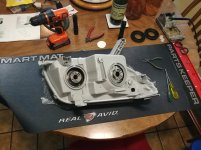
1-Headlight disas 1.jpg

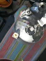
I baked the headlights at 250F for about 8 min. I recommend gloves as they will be very hot when you first pull them out of the oven. Using a flat blade or other tool, pop the clips off around the housing. From there I just pulled the housing apart instead of risking damaging the plastic further with a tool.
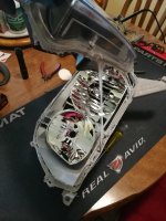
1-Headlight disas 2.jpg

NOTE: Once you separate the headlight lens from the housing, smooth the rubber sealant back evenly around the housing while it is still warm. This will make it cleaner to work with and save you a step when sealing them back up.
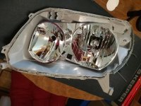
1-Headlight disas 3.jpg

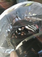
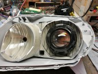
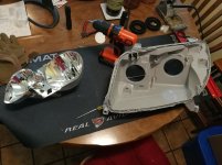
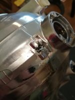
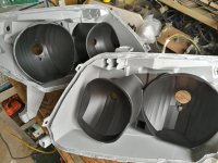
Next you can remove the headlight reflector bowl by loosening the two adjustment screws. Be careful with these as the heads strip very easily. Remove the low beam light shield by bending in the two metal clasps holding it in place.
1-Headlight disas 4.jpg
1-Headlight disas 6.jpg
 

Attachments

  • 0-Parts picture.jpg
    0-Parts picture.jpg
    141.3 KB · Views: 1,060
  • 1-Headlight disas 1.jpg
    1-Headlight disas 1.jpg
    128.1 KB · Views: 1,030
  • 1-Headlight disas 2.jpg
    1-Headlight disas 2.jpg
    129.4 KB · Views: 999
  • 1-Headlight disas 3.jpg
    1-Headlight disas 3.jpg
    128.4 KB · Views: 1,017
  • 1-Headlight disas 4.jpg
    1-Headlight disas 4.jpg
    124.4 KB · Views: 1,058
  • 1-Headlight disas 5.jpg
    1-Headlight disas 5.jpg
    117.4 KB · Views: 1,031
  • 1-Headlight disas 6.jpg
    1-Headlight disas 6.jpg
    114.9 KB · Views: 1,040
Last edited:
Register to hide this ad
Step 2: Retrofitting the reflector bowl

I used a Dremel with cutting and sanding wheel for the majority and then used a mill file for more finer work. If you have a belt sander this would be way easier and virtually guarantee a flat surface. You will still need a cutting blade in order to cut out a hole for your wires.

2-Headlight sanding 1.jpg

2-Headlight sanding 2.jpg

2-Headlight sanding 3.jpg

2-Headlight sanding 4.jpg

As you can see in the picture I went almost flat across on the back of the housing and then enlarged the hole in order to fit the projector snuggly in the housing.

2-Headlight sanding 5.jpg

You want to cut this whole big enough to fit your largest plug through. If you are doing vent halos it needs to be big enough to fit the halo wire through while the high beam wire is through.

2-Headlight sanding 6.jpg
 

Attachments

  • 2-Headlight sanding 1.jpg
    2-Headlight sanding 1.jpg
    126.8 KB · Views: 1,089
  • 2-Headlight sanding 2.jpg
    2-Headlight sanding 2.jpg
    123.9 KB · Views: 1,030
  • 2-Headlight sanding 3.jpg
    2-Headlight sanding 3.jpg
    133.1 KB · Views: 993
  • 2-Headlight sanding 4.jpg
    2-Headlight sanding 4.jpg
    121 KB · Views: 1,038
  • 2-Headlight sanding 5.jpg
    2-Headlight sanding 5.jpg
    137.1 KB · Views: 1,050
  • 2-Headlight sanding 6.jpg
    2-Headlight sanding 6.jpg
    122 KB · Views: 1,023
Last edited:
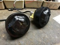
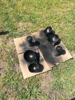
Step 3: Painting reflector bowl and DRL/High beam cluster

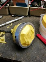
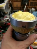
This is straight forward, scuff up the surface, clean, cover and paint. I did cut X(s) in some plastic cups which held the DRL/High beam lights perfectly.

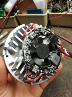
Just in case you wanted to know what's under the cover on the DRL/HighBeam:

3-DRL paint-prep 1.jpg

3-DRL paint-prep 2.jpg

3-DRL paint-prep 3.jpg

3-DRL paint-prep 4.jpg

3-DRL paint-prep 5.jpg

3-DRL paint-prep 6.jpg

3-DRL paint-prep 7.jpg

3-DRL paint-prep 8.jpg
 

Attachments

  • 3-DRL paint-prep 1.jpg
    3-DRL paint-prep 1.jpg
    130.4 KB · Views: 976
  • 3-DRL paint-prep 2.jpg
    3-DRL paint-prep 2.jpg
    128.2 KB · Views: 985
  • 3-DRL paint-prep 3.jpg
    3-DRL paint-prep 3.jpg
    129.6 KB · Views: 963
  • 3-DRL paint-prep 4.jpg
    3-DRL paint-prep 4.jpg
    113.6 KB · Views: 1,009
  • 3-DRL paint-prep 5.jpg
    3-DRL paint-prep 5.jpg
    140.3 KB · Views: 972
  • 3-DRL paint-prep 6.jpg
    3-DRL paint-prep 6.jpg
    132.7 KB · Views: 1,009
  • 3-DRL paint-prep 7.jpg
    3-DRL paint-prep 7.jpg
    127.5 KB · Views: 1,056
  • 3-DRL paint-prep 8.jpg
    3-DRL paint-prep 8.jpg
    125.5 KB · Views: 950
Step 4: Test fit everything together

Ensure that you get a snug fit on everything, put the headlight housings together and make sure it all fits together.

4-Headlight with DRL 1.jpg

4-Headlight with DRL 2.jpg

4-Headlight with DRL 3.jpg
 

Attachments

  • 4-Headlight with DRL 1.jpg
    4-Headlight with DRL 1.jpg
    124.8 KB · Views: 1,221
  • 4-Headlight with DRL 2.jpg
    4-Headlight with DRL 2.jpg
    131.7 KB · Views: 958
  • 4-Headlight with DRL 3.jpg
    4-Headlight with DRL 3.jpg
    121.4 KB · Views: 1,131
Step 5: Halo mounting on shroud vents

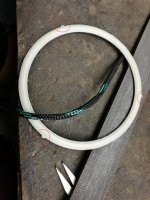
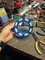
I went with mounting the halos inside the shroud which shows through the vents in the shroud. I’ve never mounted anything like this before so I went with my gut. I’m sure there are better ways but this is how I did it and it worked great.

I sanded off the factory mounting holes around the edge of the halos in order to allow them to sit flusher in the shroud.

5-Halo mounting 1.jpg

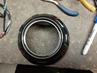
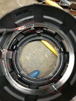
Then I started by drilling a single hole in almost the center of the shroud in a semi tri pattern. I wanted a larger gap to be facing the more visible side of the shroud when mounted in the housing. For example, the picture shows the shroud I used on the passenger side so that the wires would be more hiding by the housing and less visible. Not sure how much difference this made but it’s something to think about I suppose.

5-Halo mounting 2.jpg

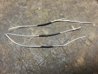
I then took some stranded wire and stripped either side, leaving just enough sheathing to blend in with the shroud.

5-Halo mounting 3.jpg

I was then able to feed the wire through the top vent and hole I cut. I then twisted the wires as tightly as possible with some pliers and solder them just for good measure. Snipped the ends and tested it.

5-Halo mounting 4.jpg

5-Halo mounting 5.jpg

5-Halo mounting 6.jpg
 

Attachments

  • 5-Halo mounting 1.jpg
    5-Halo mounting 1.jpg
    137.1 KB · Views: 969
  • 5-Halo mounting 2.jpg
    5-Halo mounting 2.jpg
    136.3 KB · Views: 968
  • 5-Halo mounting 3.jpg
    5-Halo mounting 3.jpg
    138.9 KB · Views: 955
  • 5-Halo mounting 4.jpg
    5-Halo mounting 4.jpg
    132.6 KB · Views: 960
  • 5-Halo mounting 5.jpg
    5-Halo mounting 5.jpg
    125.8 KB · Views: 1,045
  • 5-Halo mounting 6.jpg
    5-Halo mounting 6.jpg
    137.3 KB · Views: 973
Step 6: Test run

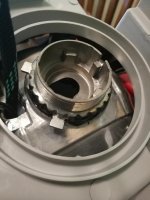
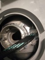
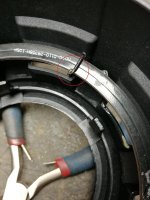
Mount the reflector bowl back into the housing, remove the housing currently on your vehicle and replace with your new unsealed housing. Don’t be lazy, use all four screws when testing your headlights as this might cause them to sit differently. Get them perfectly horizontal and tighten down the lock ring as tight as possible. I used a flat blade until I couldn’t tighten it anymore, looking back on it, I think a large socket might be better.

IMG_20180627_210304.jpg

NOTE: Take this time to get the headlights mostly aligned. You shouldn’t be pulling out the bowl anymore so when you seal them up and install them they will be almost perfect and only need some fine tune adjusting instead of the massive adjustments I had to make in very confined spaces.

IMG_20180627_210257.jpg

Step 7: JB weld/Shroud mounting

I placed small amounts of JB to “weld” the lock ring to the housing. I did this in hopes that if I wanted too, I could salvage the projector itself by just cutting off the welds on the ring/housing.

IMG_20180629_125856.jpg

I didn’t trim the shroud at all. I think it fits almost perfectly the way it is and didn’t notice in light bleed to warrant trimming the shroud and possibly ruining it. However, when you pop the shroud on it will sit up in the housing. If you apply pressure on the shroud though it will seal almost completely all the way around the housing. I placed small dabs on the shroud mounting points and held pressure against the shroud until it setup a little bit and didn’t pop up anymore. Probably about 10-15 min…

Step 8: Clean and seal

Thoroughly clean all of the dust, debris, oils etc. from the inside of the headlights (outside too so stuff doesn’t creep in when sealing). After your done cleaning them, walk away for 30 min and then go clean them again, you probably missed some. Toss them back in the oven at 250F for 8 min to heat up the rubber sealer and then compress them together making sure you work all around the seal. I didn’t but I’ve read it’s good to throw them back in the oven one more time and press the sealant around again.

IMG_20180629_160137.jpg
 

Attachments

  • IMG_20180629_125856.jpg
    IMG_20180629_125856.jpg
    115.3 KB · Views: 1,009
  • IMG_20180629_160137.jpg
    IMG_20180629_160137.jpg
    119.7 KB · Views: 1,003
  • IMG_20180627_210304.jpg
    IMG_20180627_210304.jpg
    126.2 KB · Views: 990
  • IMG_20180627_210257.jpg
    IMG_20180627_210257.jpg
    121.6 KB · Views: 991
Last edited:
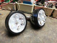
Step 9: Mount, wire, fire up and enjoy

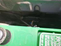
Here is where I mounted the ballast boxes on each side. Someone might have a better idea, this is working for me just fine for now though. I still am deciding where I’m going to tuck the halo drivers and harness relays. Though I might just zip tie them up and leave them how they are.

IMG_20180701_171012.jpg

IMG_20180701_171020.jpg

Here is how I wired everything up.

Projector:
OEM low beam socket with the harness and the high beam switch to the high beam socket.

Projector Vent Halos:
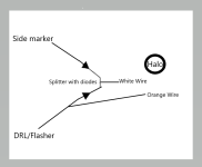
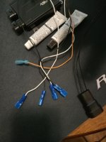
White wire goes to a homemade splitter with two 1k diodes pointing to the white wire which taps into the Side marker light (on when headlights are on) and DRL/Flasher lights (which are constant on during the day, when headlights are switched off and flashes with the turn signal). More explained at the bottom.
Black Wire goes to a plug that I made to tape into factory ground on the frame.
Orange Wire goes to the DRL/Flasher.
I just used but splice connectors for all of my connections here so that they would be easy to disconnect for any reason. I’m not a fan of cutting wires.

Halo.png

IMG_20180629_140532.jpg

DRL/High Beam LEDs:
Socket plugs into OEM high beam socket
White Wire plugs into DRL circuit.


Here are some of the issues I ran into and other misc. notes that might be useful to people.

-Halo Vent Sizes: Trust “Theretrosource.com” for their recommended vent size halos. I originally went with the 100mm per Lightwerkz.net recommendation and found they barely were big enough to shine through the vents. Really all you got was the reflection of them bouncing light off the inside of the shroud. The correct vent halos for Apollo 3s is 110mm. Note they will not sit flush in the shroud but this isn’t an issue.

-The coating on the DRL/High beam will come off with acetone…It’s not just glass. I learned the hard way.

-Sadly, I have not figured out a way for the switchback halos to always work as intended. Because I cannot isolate the 12v single when the flasher is engaged. Thus, for them to function at all they have to be tapped into the DRL/Flasher. What this obviously means though is whenever the DRL are on, they will be amber. They do work as intended when the headlights are on though, only turning to amber when the flasher is engaged.

-During the daytime, I have to keep the headlights in the off position with the high beam lever throw forward. If I do not, the opposite DRL/High Beam light will flash with the flasher. Meaning if you signal right, all of your right flashers will flash and the left DRL/High beam will also flash.

-Use coupon code "junkie" on lightwerkz.net for 10% off and free shipping. Comes in handy when you have to make several smaller orders...
 

Attachments

  • IMG_20180629_140532.jpg
    IMG_20180629_140532.jpg
    123 KB · Views: 1,005
  • Halo.png
    Halo.png
    27.7 KB · Views: 1,017
  • IMG_20180701_171012.jpg
    IMG_20180701_171012.jpg
    108.7 KB · Views: 966
  • IMG_20180701_171020.jpg
    IMG_20180701_171020.jpg
    127.8 KB · Views: 965
Last edited:
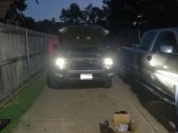
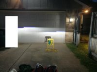
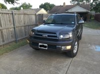
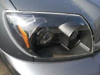
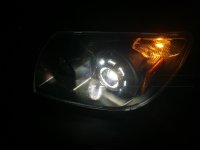
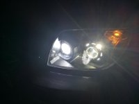
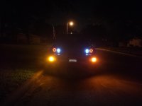
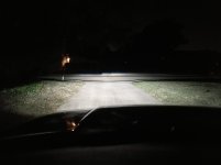
Here is the final product:

IMG_20180630_194711.jpg

IMG_20180630_164820.jpg

IMG_20180630_220122.jpg

IMG_20180630_220136.jpg

IMG_20180630_220215.jpg

IMG_20180630_215438.jpg
 

Attachments

  • IMG_20180630_194711.jpg
    IMG_20180630_194711.jpg
    137.2 KB · Views: 954
  • IMG_20180630_164820.jpg
    IMG_20180630_164820.jpg
    138.1 KB · Views: 950
  • IMG_20180630_220122.jpg
    IMG_20180630_220122.jpg
    116.3 KB · Views: 976
  • IMG_20180630_220136.jpg
    IMG_20180630_220136.jpg
    128.5 KB · Views: 985
  • IMG_20180630_215438.jpg
    IMG_20180630_215438.jpg
    118.4 KB · Views: 989
  • IMG_20180630_220215.jpg
    IMG_20180630_220215.jpg
    116.1 KB · Views: 985
Last edited:
i would like to use the nut and bolt method for extra security. but good job.

remember with your height a 3inch drop at 25ft is prefered.
2.5 is really high for our trucks.
 
So the DRL function on the High beam/Profile you tapped into the factory drl/turn ? Is there a reason you did that over the city/side marker light in the headlight?

Really good looking set up though.
 
So the DRL function on the High beam/Profile you tapped into the factory drl/turn ? Is there a reason you did that over the city/side marker light in the headlight?

Really good looking set up though.

I might be wrong, but the side marker light is only on when the headlights are on correct? That's the only time I have seen it illuminated at least.
 
I might be wrong, but the side marker light is only on when the headlights are on correct? That's the only time I have seen it illuminated at least.

Believe you are correct, not saying anything was wrong with that and that's a good point. Just didn't know if that would be better then having it tied into the DRL/Turn functionality.

I have been eyeing those high beams and really like how they look in there :thumb: really helpful guide, appreciate you posting it.
 
I’m glad I came across this post! I’ve been trying to make up my mind about going ahead with a g5r retrofit with a profile hi lens in the high beam or waiting until the morimoto mini d2s 5.0 comes out *supposedly* in the coming months. I’ve been really conflicted over what to do with the high beam—how does the hi lens work for you? I’ve seen mixed reviews on it and want to make damn sure before I pull the trigger. Is it a significant improvement over your stock high beam? Does it make a noticeable difference on top of the g5r high beam function? I’d hate to install it if it’s not even noticeable in addition to the g5r high function. Your setup looks great and regardless of the route I go your write up will help a lot!
 
. I’ve been really conflicted over what to do with the high beam—how does the hi lens work for you? I’ve seen mixed reviews on it and want to make damn sure before I pull the trigger. Is it a significant improvement over your stock high beam? Does it make a noticeable difference on top of the g5r high beam function? I’d hate to install it if it’s not even noticeable in addition to the g5r high function. Your setup looks great and regardless of the route I go your write up will help a lot!

So the way I looked at it was my g5rs were already my acting low and high beams so, therefore, my high beam spot served more cosmetic purposes.

Don't get me wrong though, the hi lens is super bright...but when you shine a very bright light (the g5r) on top of another bright light in the same position...it doesn't make as much of a noticeable difference. But I also never ran them installed independently so I can't say for certain if the hi-lens do add a lot or not. On the flip side of it though, looking at the lights you'll def notice when the hi-lens come on vs their normal running light mode.

I can say though that when running high beams this setup lights up everything.

Let me know if you run into any issues and what you end up doing! Aside from how much time and all my setbacks this was actually a really satisfying project.
 

Members online

Forum statistics

Threads
278,316
Messages
3,554,120
Members
248,016
Latest member
Advally Service

Trending content

Back
Top