LED Electrical wiring question

Myrunr2010

New member
I am getting ready to wire up some LED lights in my rear bumper. The plan is to have them come on when the vehicle is in reverse, and also wired to an auxiliary switch on the dash so that I can turn them on without the vehicle being in reverse. This is what I bought. They are 18w LED lights. This is the wiring harness for the dash switch. It says it comes with the follow: Includes Laser SPST On/Off Rocker Switch, 40A Power Relay, 30A Blade Fuse, more than 12ft wire & connector kits.

My question is, do I need any additional relays/fuses in line? My plan right now is to run the first power wire and tap into the reverse lights power wire right at the tail lights. The wire going to the dash will tap in off of the original power light coming off of the lights. Does that sound right? Do I need anything extra or is that it?
 
Register to hide this ad
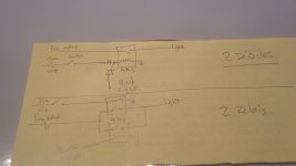
There's lots of way to do this with 2 diodes....one for the reverse light wire and one for the switch wire...or 2 relais one for the reverse light and one for the switch....ill try do draw it and send it to you....:art:
 
I used an extra relay i had laying around and grounded it to the body and used power from the battery. Then ran it to the rocker switch from there, then off to the actual lights. Thats just what i did for my front cubes but on my led rear bumper lights i just tapped into the factory reverse power at the tail light. Sounds like you have a solid plan though. Best of luck!

Sent from my SM-J320P using Tapatalk
 
I'm not 100% on the up and up about car wiring/how it works. I understand house wiring just fine, and have no issues splicing wires together and what not given instructions. Can someone explain to me exactly what a relay does? I guess the online fuses that people put are to keep the battery from pushing too many amps/Volts and blowing your lights, or is it the other way around where the lights potentially draw too much power? Just trying to better understand car wiring and the theory behind it.
 
I'm not 100% on the up and up about car wiring/how it works. I understand house wiring just fine, and have no issues splicing wires together and what not given instructions. Can someone explain to me exactly what a relay does? I guess the online fuses that people put are to keep the battery from pushing too many amps/Volts and blowing your lights, or is it the other way around where the lights potentially draw too much power? Just trying to better understand car wiring and the theory behind it.


What is a relay?

A relay is an electromechanical or electronic device through which a heavy load can be switched ON & OFF with a nominal input of current & voltage. This article focuses on electro-mechanical relays used in automotive applications.

How does a relay work?

The utility and function of a relay can be best understood by thinking of a lever. A lever is inserted at a corner of a heavy load and by placing a wedge (fulcrum) under the lever, the heavy load can be easily lifted by a small amount of effort.

Similarly, a heavy electrical load drawing heavy current can be switched on & off by applying a small amount of current through a coil(solenoid). What happens is this - the coil gets magnetized with the current and attracts or repels a plunger(a rod passed through the coil). The attracting or repelling of the plunger either connects two switching contacts in the relay (also known as NO or Normally Open/Single Throw/Form A) or separates them (NC or Normally Closed/Double Throw/Form C), as required. As soon as the energisation of the coil is stopped, the main contacts go back to their original position.

In automobile applications relays of different configurations with single or multiple contacts are used for different applications.

Why is a relay required?

Apart from switching a circuit with heavy load, on & off, a relay is required to

1. Conserve energy

2. Prolong the life of device

3. Improve the efficiency of a device.

For example let us take the switching of two headlamps of an automobile. If the same is switched on through a normal switch at the dashboard, the voltage drop from the battery to the lamps through the switch will be enormous and the heat generated in the circuit due to resistance will be considerable. The heavy current will be drawn by the lamps which will not only heat the circuit but also drain the battery heavily.

To give an example of the effect of voltage drop, a chart is given below:

Operating Voltage. Luminous Intensity of a Lamp.
100% 100%
95% 83%
90% 67%
85% 53%

To switch on a 12V-60/100 Watt Halogen lamp, a typical 12V Relay allows a voltage drop of only 0.02V and the coil current is only 2 milliamps.

Another important function of the relay is quick switching off(0.05Sec Max.). The more time the contacts of a switch take to break at full load, the more sparks will be generated due to electromagnetic effect on contacts in a switched on state. Prolonged sparking will mean more wear of the contact points and the danger of contacts melting and generating a fire. International standards have very stringent relay specifications. The endurance of a relay is generally specified in millions of switching operations.


Source: http://www.fourthgen.net/automotive-relays-functions-uses.shtml

 
I'm not 100% on the up and up about car wiring/how it works. I understand house wiring just fine, and have no issues splicing wires together and what not given instructions. Can someone explain to me exactly what a relay does? I guess the online fuses that people put are to keep the battery from pushing too many amps/Volts and blowing your lights, or is it the other way around where the lights potentially draw too much power? Just trying to better understand car wiring and the theory behind it.

I've subscribed to this thread as I too am learning about this stuff. From recent reading, I think the fuse is just the safe blowout point to protect the whole system in the event of overload. So they put them next to the battery. And the relay is there to handle the heavy loads to keep that much juice from being in the cab with you. I guess it's not wise to have enough juice to run headlights (or whatever) flowing into the actual headlight switch in the cab, so the the switch is run to a relay that in-turn handles the actual opening/closing of that circuit. Basically it keeps the juice away from you.

I don't know much about this stuff yet so don't pay any attention to me. I'm just stoned.
 
With a relay you use small load to trigger a big load. So the switch sends 12v and triggers the relay which then. Turns on your bigger item. Safely.
 
Ok here it is if you have questions Just ask
 

Attachments

  • 20160821_185347.jpg
    20160821_185347.jpg
    135.3 KB · Views: 383
Ok here it is if you have questions Just ask

Let me see if I got this right. Wire connected to the battery, then fuse, wire continues in through the firewall. Once in the cab power would connect to the relay and then to ground. There would be a second set of wires from the relay, once to the switch, the second to the lights out back? I assume the switch would have a second wire that would go to ground?
 
One thing I'll say about this whole switch vs relay thing that I think always gets lost -

Switches can handle large current just fine, if you buy an appropriately spec'd switch. Just don't buy the first one you see off amazon and assume it will work / be safe. But then you are running high currents in and out of the dash, etc, and all with thick gauge wire.

One of the biggest reasons for a relay and switch is the control wire - meaning smaller gauge wire that is used on the switch to power the relay solenoid, and then larger gauge wire to handle the current of the load.

Voltage has nothing to do with it - its all the current. We design 20+ conductor 22awg cable to carry 125VDC in my industry all the time, using just 0-1mA signals. Wires/switches primary depend on the ampacity / current capacity.
 
One thing I'll say about this whole switch vs relay thing that I think always gets lost -

Switches can handle large current just fine, if you buy an appropriately spec'd switch. Just don't buy the first one you see off amazon and assume it will work / be safe. But then you are running high currents in and out of the dash, etc, and all with thick gauge wire.

One of the biggest reasons for a relay and switch is the control wire - meaning smaller gauge wire that is used on the switch to power the relay solenoid, and then larger gauge wire to handle the current of the load.

Voltage has nothing to do with it - its all the current. We design 20+ conductor 22awg cable to carry 125VDC in my industry all the time, using just 0-1mA signals. Wires/switches primary depend on the ampacity / current capacity.

Yea. Correct. There are switches that can handle the amps/volts of the accessory. But the relay acts as a safe precaution. If somethings happens you don't want your switch to melt. So a relay is a good safe precaution in my head.

Let's get something cleared. If there was no need for relay. Car manufacturers wouldn't use it either. I'm sure they can source proper switches.

I currently have a USB outlet wired through a 3M switch which is rated for 20 amps. And I have no relay for the USB outlet. I simply have it wired like this. A blue sea aux fuse box. From the fuse box a wire goes to my switch. From the switch it goes to the outlet. In the blue sea box. I have a 5amp fuse that's it.
 
Last edited:
Yea. Correct. There are switches that can handle the amps/volts of the accessory. But the relay acts as a safe precaution. If somethings happens you don't want your switch to melt. So a relay is a good safe precaution in my head.

Let's get something cleared. If there was no need for relay. Car manufacturers wouldn't use it either. I'm sure they can source proper switches.

I currently have a USB outlet wired through a 3M switch which is rated for 20 amps. And I have no relay for the USB outlet. I simply have it wired like this. A blue sea aux fuse box. From the fuse box a wire goes to my switch. From the switch it goes to the outlet. In the blue sea box. I have a 5amp fuse that's it.

Well, one example is this:

Look at the ignition system - there are 5(iirc) heavy gauge wires running through the ignition column. Plenty of space there.

Now imagine all those thick wires trying to do something like a headlight stalk, or something of the sort. That's where the small control wires come in hand for the relays.

The other biggest example is all the digital crap in cars these days... A PCB can't drive a headlight circuit, but it can easily drive a relay.
 
So let me ask this. If I tap into the existing backup light wiring, and they only come on when the backup lights are on, I should have no need for any additional fuses or relays, right? Because they would already be built into that circuit?
 
Let me see if I got this right. Wire connected to the battery, then fuse, wire continues in through the firewall. Once in the cab power would connect to the relay and then to ground. There would be a second set of wires from the relay, once to the switch, the second to the lights out back? I assume the switch would have a second wire that would go to ground?

Yes youre right if youre switch has a light....
And for one diode , i think that if you're switch as a light you could ground the b.u.light wire and blow youre fuse......
 
So let me ask this. If I tap into the existing backup light wiring, and they only come on when the backup lights are on, I should have no need for any additional fuses or relays, right? Because they would already be built into that circuit?

Assuming you are using the relay that came with your kit, and the back-up light circuit is tapped as the trigger for that relay coil, you don't need anything more. There is no relay built into the back-up light circuit, it pulls power from the 10A GAUGE fuse (which has a pantload of other stuff on it) and is controlled by the park/neutral switch--there is no relay in that circuit.

It will work fine to trip your add-on relay. It should NOT be used to power the aux. lights directly (just to be clear.)

Back-up light circuit here: http://tacoma.site40.net/4Runner_96-02_Repair&Wiring/techinfo.toyota.com/ileaf/ewdtmc2/ewdtmpdf/ewdsourc/2002/024runne/systemci/027bl.pdf

And yeah, you only need one diode (to keep stock back-up lights off when using the switch for the aux. lights). You just need to source power for the switch, if used, from somewhere in the GAUGE circuit. You don't want two different fuses feeding the relay coil if both back-up light switch and manual switch are closed. Bad things can happen if there is a short in that situation. The second diode does protect against that issue but I like it simple. Getting power from the same fuse (GAUGE) takes care of that and eliminates need for a second diode.
 
Last edited:
Assuming you are using the relay that came with your kit, and the back-up light circuit is tapped as the trigger for that relay coil, you don't need anything more. There is no relay built into the back-up light circuit, it pulls power from the 10A GAUGE fuse (which has a pantload of other stuff on it) and is controlled by the park/neutral switch--there is no relay in that circuit.

It will work fine to trip your add-on relay. It should NOT be used to power the aux. lights directly (just to be clear.)

Back-up light circuit here: http://tacoma.site40.net/4Runner_96-02_Repair&Wiring/techinfo.toyota.com/ileaf/ewdtmc2/ewdtmpdf/ewdsourc/2002/024runne/systemci/027bl.pdf

And yeah, you only need one diode (to keep stock back-up lights off when using the switch for the aux. lights). You just need to source power for the switch, if used, from somewhere in the GAUGE circuit. You don't want two different fuses feeding the relay coil if both back-up light switch and manual switch are closed. Bad things can happen if there is a short in that situation. The second diode does protect against that issue but I like it simple. Getting power from the same fuse (GAUGE) takes care of that and eliminates need for a second diode.

You have slightly exceeded my knowledge level...

What why I not want to wire the aux lights directly into the reverse light circuit?

Btw, hows the frame swap going?
 
You have slightly exceeded my knowledge level...

What why I not want to wire the aux lights directly into the reverse light circuit?

Btw, hows the frame swap going?

The amp draw on those aux. lights is 2x18w or 3 Amps [MENTION=133652]12volt[/MENTION]s. That's more than I would want to tack on to the light 10A GAUGE circuit given how much runs on that. Also, that fuse feeds many critical systems you don't want to lose while driving for a fault in an aux. light.

Swap is proceeding. Weather has improved. Almost ready to paint.
 
Last edited:
The amp draw on those aux. lights is 2x18w or 3 Amps [MENTION=133652]12volt[/MENTION]s. That's more than I would want to tack on to the light 10A GAUGE circuit given how much runs on that. Also, that fuse feeds many critical systems you don't want to lose while driving for a fault in an aux. light.

Swap is proceeding. Weather has improved. Almost ready to paint.

What all runs on that circuit? I lost my gauges this morning, window function and heat
 
What all runs on that circuit? I lost my gauges this morning, window function and heat

I don't remember them all, but it's the circuit that tells a number of systems the ignition is on and it's OK to run. Heat, windows, rear defog, seat belt warning, window washer, are some. Those all have primary circuit power, but without GAUGE they think the truck is off and they stay dead.
 

Members online

No members online now.

Forum statistics

Threads
278,306
Messages
3,554,045
Members
248,016
Latest member
Advally Service

Trending content

Back
Top