My installation experience, instructions -4th Gen -- & endorsement of the kit!
Dane,
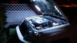
I finished installing my kit this Thursday, and I love it.
I wanted to let everyone know that it's incredibly well made, and of high
quality. Thank you, Dane.
THIS KIT HAS MY HIGHEST ENDORSEMENT.
With that said, I wanted to share a few issues that I dealt with during my installation. THESE WERE NOT DANE's fault, rather they were a few SMALL problems that I had, and a few small mistakes that I made.
So, I thought I would post about my particular issues, and try to write up instructions on the installation to save others from my silly mistakes, and to clarify the small confusions that I had.
Let me repeat. THIS IS NOT A CRITICISM.
DANE MAKES AN INCREDIBLY HIGH QUALITY KIT, AND I RECOMMEND IT, WITHOUT RESERVATION, IF YOU WOULD LIKE A LIGHT UNDER YOUR HOOD. This is the best you can get, and it is awesome.
With that endorsement plainly stated. Below were my experiences along with my humble attempt to document installation instructions.
Issue 1) I wasn't sure how everything hooked up. I consider myself a sharp guy, but I was a little confused at first. I soon figured it out, but I'm also adding this write-up in case others are similarly confused.
Status: SOLVED.
Issue 2) I had trouble with the high quality female crimp on spade connectors in the kit.
For the female, crimp on spade connectors, every one that I crimped either wasn't tight enough, or was so tight that it broke off the wire. I
*thought* I was good at this. I have two of your more common "cheap" crimpers, and one high quality, rather expensive crimper.
When I tried the cheap crimper, the wire was thin, and the connector was loose.
When I used the high quality crimper, the soft thin wire broke off inside the connector. I just couldn't get it right!
I ended up using my own, cheaper crimp on connectors and high quality electrical tape to seal it. I'll probably go back and apply heat shrink over everything including the tape.
I don't know why I had this trouble. I'm serious when I say that Dane supplied high quality crimp on connectors. His are the more expensive kind that include heat shrink tubing built onto the connector so that you can have a good, watertight connection, but for some reason I had problems with the ones that were provided.
Status: SOLVED. (I used cheaper connectors that worked for me.)

I'd like a kit for a 4th gen.
I'd like to request that my kit have BOTH a hood pin AND a toggle switch... thus the light will turn on and off when the hood is open and closed, but I'll also have a toggle switch to permanently turn it off... that way I can't forget and leave the light on with the hood closed, but I can also use the toggle switch to keep the light off, so I can open the hood and not look like a light house when I'm outdoors!
It's fine for the toggle switch to mount under the hood. That keeps it simple.
Thanks for the kit with both switches.
I'll chime in below with a few installation tips.
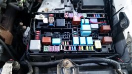
Yeah that's the switch that comes with it and you'll get all the connectors as well. Real easy job. If you add a switch then you'll have to spice that in and mount it somewhere. Personally if I wanted the lights off with the hood open id just pull the wire from the hood pin or pull the fuse.
So I consider myself a bright guy, but it took me a while to figure out what to do. Of course, going to the truck and loosely laying everything around and looking under the hood helped clear up A LOT for me.
The hook kit is easy because everything is right there. Your just connecting the red to the battery and the black to the underside of the hood pin.... Here's where I put the pin under my hood.
[MENTION=69687]Tucson4runner[/MENTION] is correct.
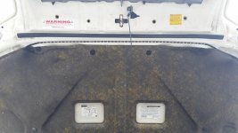
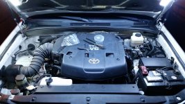
--> Step 1: TEST FIT) -- look under your hood with your kit in hand, and loosely hold the kit up to see where it will mount.
--> Step 2: CLEANING PREP) -- Clean the mounting surfaces well with alcohol or mineral spirits, or windex, etc, so that you aren't trying to stick to a dirty surface.
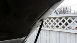
--> Step 3: INSTALL CENTER LIGHT STRIP) -- Locate the center part of the center light. Hold your finger there as a way of marking that spot. Pull the backing off starting at the center, and you can apply the center piece starting from the center of the hood. Pay attention to run it so that your hook up wires will end up on the side of the truck near the battery.
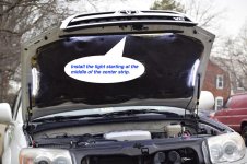 --> Step 4: PLAN AND ROUTE SIDE LIGHTS)
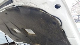
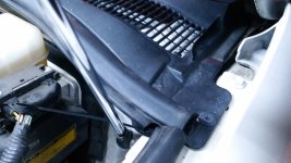
 Determine how you want to route the wires connect to the two side light strips. I decided to snake them behind the hood pad myself, although based on the length of the wires, it seems that it was intended for the wires to simply go around the edge of the hood. NOTE: I didn't realize that the hood pad will crumble easily. It's almost like well-baked cardboard. Now I know. Don't try to take the pad off, ir fit your hand behind it. If you do go behind the hood pad, use the light strip itself to fish the passenger side behind the pad.
On the driver's side, use the wires, or choose your favorite "fish tape" type of solution, and temporarily connect the wire to it via duct tape or any other suitable means to fish the wire and the light strip behind the hood pad on the driver's side.
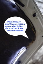
--> STEP 5: INSTALL SIDE LIGHT STRIPS ) This is dog-simple. Peel the backing off each side (one at a time), and stick them where they below.
--> Step 6: INTALL 2 to 4 OF THE ZIP TIE SUPPORTS ) You want to peel the backing off the small plastic squares, and stick them where they can support the wires for the two ends of the center light strip. Mount the supports so that they will not have interference when you close the hood. Use the zip ties to secure the wires to these parts.
--> Step 7: RUN THE WIRE INTO THE ENGINE BAY )
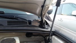
I decided to run my wire though an existing slot in front of the windshield.
On the driver's side of the firewall, there is an existing wire that runs into that space, and about 1.5" or so rubber plug that the wire runs through. I decided to remove this plug, and run my wires through it too. It was difficult to remove the electrical tape on the back of this plug and not worth it to me to put in the time, so I used a small knife to make a new slit in the rubber, and with some stretching and pulling on the rubber of the plug and some needle nose pliers, I was able to fish the wire and it's looming through the rubber plug. Leave a enough free play so that you aren't straining the wire when the hood if fully opened. Then put the plug back.
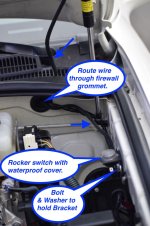
--> Step 8: IF YOU HAVE A TOGGLE SWITCH, MOUNT THE BRACKET FOR IT)
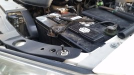
I did a test fit of the switch into the bracket. I decide to cut a small notch in the plastic mounting bracket to accommodate the small notch on side of the switch. Put the washer on the bolt and feed it through the hole in the switch bracket. Use a wrench or ratchet (preferred) or pliers to thread the bolt into a pre-existing threaded hole on the inside of the engine bay on the driver's side of the engine bay wall. My hole had factory paint in the threads, so I needed to use hand tools, even to get the bolt started, but it wasn't hard. I just turned it slowly by hand, and the bolt screwed in, clearing the threads of the paint as I screwed it in.
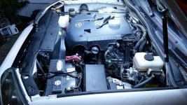
--> Step 9: PLAN WHERE YOU WILL ROUTE YOUR POWER WIRES AND GROUND WIRES) Look, lay it out, and think about it.
--> Step 10: INSTALL YOUR POWER WIRE & SWITCH)
Simply run the wires straight along the driver's side of the inside of the engine bay. If you do this, the wire looming will easily reach to a good location where you intend to ground the circuit. If you have a switch, you need to make a hole in the looming below the switch, separate the end of the red wire from the black wire, and pull the red end through the hole in the looming.
Now you can leave an inch or two of length on the red wire, and cut it, and attach the crimp on connectors to the red wire. THE CRIMP ON CONNECTORS SUPPLIED ARE A GOOD KIND (they have heat shrink tubing built on to them), but I couldn't use them -- or I was using them improperly. I tried using my crimpers, and everytime I tried it failed to connect the wire. I end up using my own inferior crimp on connectors, and good quality electrical tap to wrap them carefully so they are weather tight.
FOR THE SWITCH ROCKER SWITCH -- it comes with a nice, water proof cover. I hadn't used one before, so I kept trying to install it the wrong way. Here's the scoop. It's easier than I thought. The water proof cover has a small, split lip around the edge. This split lip fits snugly over the bezel built onto the switch. Pull the two ends of the red wire through the hole, and hook the wires up to the switch -- the center connector and one of the ends, and the gently push the switch into the mounting hole, so that the wires come out the bottom.
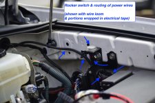 --> STEP 11 INSTALL YOUR FUSE)
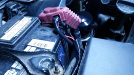
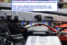
 Cut the red wire on the fuse. I left about one inch of wire on one side, so that their was a longer piece of wire on the other side. Strip a little wire and crimp the ring connector on the the long end of the wire. Strip a little of the other end, and the end of your power wire, and use the crimp-on butt connector to connect these two ends together.
I then used electrical tape to wrap a protective layer around all of the exposed parts of the red power wire. This is just to give the wire's sheath some protection against drying, cracking with age and rubbing.
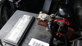
PUT THE FUSE IN THE FUSE CONNECTOR, route the red wire, and connect the ring at the end to your positive battery terminal.
 --> Step 12: INSTALL YOUR GROUND WIRE & CONNECTOR OR SWITCH)
If you don't have a hood pin, then apply the crimp on ground ring, and ground it either directly to the negative side of the battery, or by bolting it to bare metal somewhere appropriate on the chassis.
If you have a hood pin switch, find a suitable location to mount it, drill a hole if necessary or otherwise prep the location, and the mount the hood pin switch.
I partially removed the plastic trim along the front edge of the engine bay. I did this by using a small flat blade to pop up two the black "push pin" connectors that held it on. This allowed me to lift up enough of the trim to see what was under it. Near the driver's side edge of the trim, hidden by the plastic itself, there was an existing, unused hole that was a good size for the hood pin switch. I trimmed off a semi-circle from about the last 1 inch of the plastic trim. This allowed access to the hole, even when the trim is re-installed.
I used a small knife, and carefully removed the paint right around the hole, so that the hood pin & it's start washer would contact bare metal.
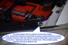
Then I used blue lock-tite on the threads of the hood pin, and installed the hood pin in the hole, using two sets of pliers to tighten it down securely. (one set to hold the nut underneath, and the other needle nose set to tighten the nut on top that was closest to the truck's frame.
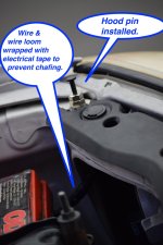
Then install a crimp connector to the end of the ground wire. Use heat shrink or electrical tape to neatly seal the wire looming to the crimp connector, and plug the ground wire connector onto the bottom flat spade of the hood connector. The hood pin will now connect to ground when the hood is open, completing the circuit so that your light can come on, and it will disconnect the ground when you close the hood, turning your light off.
I also looked at where the looming on the ground wire might rub against some metal on the truck's frame, and I wrapped several layers of electrical tape around the outside of the looming for about two inches near the part that might rub.
 --> Step 13 CONNECT THE REST OF YOUR FASTENERS )
 Use the rest of your zip ties and stick on fasteners to secure your wires. Trim the loose ends with wire clippers.
--> Step 14 APPLY HEAT TO ALL HEAT SHRINK CONNECTORS OR HEAT SHRINK TUBING IF YOU USED ANY) I used a heat gun.
--> Step 15 TEST YOUR SYSTEM & FIX ANYTHING YOU MISSED )
Test your system. With the hood open, the light should be on. If you have a rocker switch too, in one position the light should be on when the hood is open.
In the other position, the light should be permanently off. When you close the hood, make sure that the hood pin turns off the light by disconnecting the ground.