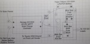
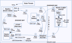
Here is a revised version of the wiring diagram.
Ground is now to the negative terminal of the starter battery. The 60A fuse on Wire #7 near that terminal, as well as the Big 3 ground wire, will protect against current potentially damaging the dual battery system components through Wire #7 if the OEM ground wire fails. The negative bus bar will be mounted in the rear of the engine bay, driver's side, on the front left fender.
The DC-DC charger's 50A maximum charge current will help charge the auxiliary battery quickly. The charger will be installed behind the right headlight. I hope the airflow cooling in this location will keep the charger internal temperature below 130 degrees F, since the charger begins to reduce its output charge current at that point.
RedArc suggests the charger be installed within 1 meter of the auxiliary battery. In this design, it's more than 1 meter away, but using 2 AWG to the auxiliary battery positive terminal keeps the charge voltage that arrives at the auxiliary battery positive terminal above 14.5V if RedArc's Charge Profile "A" (14.6V absorption) is selected instead of its Lithium charge profile. 14.5V absorption falls within the 14.4V to 14.8V range required by this particular auxiliary battery.
The LiFePO4 auxiliary battery will be installed in the rear of the engine bay, passenger side. Exposure to excessive heat here will reduce the lifespan of the battery. But if the battery is always charged well before it reaches a low SOC, the Trojan Trillium performance graphs show the battery will still have at least 1000 or 2000 charge cycles, which is more than I will need. Putting the DC-DC charger and auxiliary battery in the engine bay helps keep high amperage out of the passenger cabin and avoids taking up valuable space in the cabin. LiFePO4 will provide higher battery capacity (Wh) than a similarly sized lead-acid or AGM battery.
Circuit Wizard - Blue Sea Systems was very useful in calculating wire gauges, given the current required, the total circuit length (power source to device to ground), and various factors that affect heat dissipation from the wire.
There is exactly one 4 AWG wire through each of the two grommets (passenger side and driver's side) in the firewall.
This design limits the current going to the Blue Sea 7748 fuse block to 65A, but for safety, I will make sure the total current going to the fuse block at any one time never exceeds 50A. Most times, it will be a lot less than that.
I believe the 270XP outputs fixed voltage (14.8V) and is temperature-compensating, so the blue wire from the RedArc BCDC1250D does not need to be connected to anything.