shilly
New member
The previous threads showing the wiring for the rearview mirror show solutions to get 12 V ignition switched power from a mirror that only have 2 wires in the connector. 1) Blue (+) and White (-) on a connector with 2 rows of 5 holes. LINK and 2) Yellow (+) and white/black (-) - mentioned by Harper7 for 2003. LINK
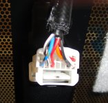
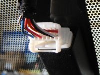
I have a 2010 SR5 with the rearview monitor built into the rearview mirror. It has a connector with (7) wires in a connector with 2 rows of 7 holes (see picture). Does anyone have a diagram indicating the proper 2 wires to get ignition switched power before I go cutting into the wires and mess something up? The wires are like 22 gauge and the connector is too tight to get my volt meter points into it.
bottom row - from left - blue with green dot - black &white - red - empty - empty - black - white
top row - from left - empty - empty - empty - empty - empty - orange - red
Any help would be appreciated
I have a 2010 SR5 with the rearview monitor built into the rearview mirror. It has a connector with (7) wires in a connector with 2 rows of 7 holes (see picture). Does anyone have a diagram indicating the proper 2 wires to get ignition switched power before I go cutting into the wires and mess something up? The wires are like 22 gauge and the connector is too tight to get my volt meter points into it.
bottom row - from left - blue with green dot - black &white - red - empty - empty - black - white
top row - from left - empty - empty - empty - empty - empty - orange - red
Any help would be appreciated