
You are using an out of date browser. It may not display this or other websites correctly.
You should upgrade or use an alternative browser.
You should upgrade or use an alternative browser.
Okki's Build Thread
- Thread starter Okki
- Start date

What tires / wheels you running these days?
Since my lay-off in September, I've not made any further mods... The list of wants has grown, but until I'm back to being fully employed, not much will be happening.
In reference to your question; stock Limited 20inch rims and tires.

Unemployment is a *****. Out of 123 applications only 4 resulted in a face-to-face interview. :toilet: Not a very good ratio.

FactoryRide
New member
Okki,
I was looking at the diagram you have for your aux fuse box and was thinking about doing one, and possibly a second one in the rear. I have a good many electrical ideas for the 4runner and thought this would help clear the clutter to the battery. I have 4 lights on the front end, soon to have one 3000w class D amp and possibly another four channel amp of some kind, CB radio, 4 lights across the roof on the front and another two on the back. So what I would really like to know would be how hard was the install? Any advice or things you would do different if you redid it?
I was looking at the diagram you have for your aux fuse box and was thinking about doing one, and possibly a second one in the rear. I have a good many electrical ideas for the 4runner and thought this would help clear the clutter to the battery. I have 4 lights on the front end, soon to have one 3000w class D amp and possibly another four channel amp of some kind, CB radio, 4 lights across the roof on the front and another two on the back. So what I would really like to know would be how hard was the install? Any advice or things you would do different if you redid it?
Okki,
I was looking at the diagram you have for your aux fuse box and was thinking about doing one, and possibly a second one in the rear. I have a good many electrical ideas for the 4runner and thought this would help clear the clutter to the battery. I have 4 lights on the front end, soon to have one 3000w class D amp and possibly another four channel amp of some kind, CB radio, 4 lights across the roof on the front and another two on the back. So what I would really like to know would be how hard was the install? Any advice or things you would do different if you redid it?
The install wasn't all that hard, but took a good bit of time. I like the position of my switch banks, but while the contura switches are awesome, with them being that low on the dash, you cannot see the symbols on them. It's no big deal for me, (blue is compressor, orange lights are front to rear of vehicle: bumper, front roof, rear roof). I'm not sure if there is a better switch for that location though.
The only "awwhhh ****" moment I had was with the compressor switch.


As you can see, I cut out the entire OEM switch area; that was a bad idea. You only want to cut out the inset area. I ended up with a housing that needed JB Weld plastic epoxy in order to remain secure.

you can just see the thin line on the left of the housing (I used some touch-up paint to blend it in). I do hit the compressor switch with my knee climbing into the vehicle every so often, but that might also be reduced if your switch sits more recessed. Ideally I would have used flat switches like the OEM RSCA switch etc.
Working under the dash is a ***** (my right hand has the scars to prove it), so get your wire harness done and pulled in one go if possible. That was my main reason to include all the leads for the additional lights and compressor that I want, but not yet have.
Feel free to PM with any other questions.
Okki
Perhaps it was mentioned elsewhere but want to thank Okki for the pics on the Hella horn install and mention that much to my surprise; I only had 1 factory horn and 1 factory wire despite Okki's pics showing 2 factory horns. I have the SR5 so must be another cost saving strategy for Toyota. That being said I couldn't use the factory harness. I cut the factory spade connector off and soldered a Y connection and added after market spade connections and then did the ground wires like Okki suggested. Everything works great! Thanks again.

DannyLlama
Elite Member
Since my lay-off in September, I've not made any further mods... The list of wants has grown, but until I'm back to being fully employed, not much will be happening.
In reference to your question; stock Limited 20inch rims and tires.
Unemployment is a *****. Out of 123 applications only 4 resulted in a face-to-face interview. :toilet: Not a very good ratio.
Okki - what kind of work do you do?
have you considered going through agencies?
Okki - what kind of work do you do?
have you considered going through agencies?
I'm a Senior Project Manager... and back at work since January. It's a consulting gig, which wasn't my first choice, but it's paying the bills

Okki
Cobra ST 75 CB with 4ft Firestik Antenna (1/7)
CB Installation in 2010 4Runner Limited.
CB Radio
Cobra 75WXST 40-Channel CB Radio $91.77 Amazon.com
Cobra AC 702 4ft microphone extension cable CBRAC702 $15.64 Amazon.com
FIRESTIK 3 Heavy Duty Stainless Steel Antenna Spring SS-3H $11.95 Amazon.com
Shipping $ -
4' Firestik(R) II FS Series Tunable Tip CB Antenna - 900 Watts Black FS-4BK $18.19 Amazon.com - Winchels Electronics
Shipping $5.98 Amazon.com - Winchels Electronics
POWER / SWR METER CB Radio 100 Watts w/ 3' Jumper cable - Workman SWR3P & CX-3-PL-P $20.75 Amazon.com - tintnelectronics
Shipping $5.49 Amazon.com - tintnelectronics
DIA-K400-3/8C : Diamond 3/8"-24 Trunk/Hatch Mount $73.95 dxengineering.com
Shipping $6.80 dxengineering.com
16ft Coax Cable: RG316/U Clear Jacket M17/113/RG316 Thermax,
1 x Male Connector: Mini UFH RFU-601-3, 1 x Female Connector: Mini UHF RFU600-3. $ 36.60 rfparts.com
Assembly $14.00 rfparts.com
Shipping $10.00 rfparts.com
Total $311.12
The first thing to do is to order your parts. One mistake I learned the hard way is that you’re probably better off to order the custom antenna extension cable readymade instead of ordering the parts and trying to build the cable yourself. I spent an extra $50 in “education money” finding that out.


Also, DO NOT run your CB without an antenna connected.

CB Installation in 2010 4Runner Limited.
CB Radio
Cobra 75WXST 40-Channel CB Radio $91.77 Amazon.com
Cobra AC 702 4ft microphone extension cable CBRAC702 $15.64 Amazon.com
FIRESTIK 3 Heavy Duty Stainless Steel Antenna Spring SS-3H $11.95 Amazon.com
Shipping $ -
4' Firestik(R) II FS Series Tunable Tip CB Antenna - 900 Watts Black FS-4BK $18.19 Amazon.com - Winchels Electronics
Shipping $5.98 Amazon.com - Winchels Electronics
POWER / SWR METER CB Radio 100 Watts w/ 3' Jumper cable - Workman SWR3P & CX-3-PL-P $20.75 Amazon.com - tintnelectronics
Shipping $5.49 Amazon.com - tintnelectronics
DIA-K400-3/8C : Diamond 3/8"-24 Trunk/Hatch Mount $73.95 dxengineering.com
Shipping $6.80 dxengineering.com
16ft Coax Cable: RG316/U Clear Jacket M17/113/RG316 Thermax,
1 x Male Connector: Mini UFH RFU-601-3, 1 x Female Connector: Mini UHF RFU600-3. $ 36.60 rfparts.com
Assembly $14.00 rfparts.com
Shipping $10.00 rfparts.com
Total $311.12
The first thing to do is to order your parts. One mistake I learned the hard way is that you’re probably better off to order the custom antenna extension cable readymade instead of ordering the parts and trying to build the cable yourself. I spent an extra $50 in “education money” finding that out.
Also, DO NOT run your CB without an antenna connected.
Last edited:
Cobra ST 75 CB with 4ft Firestik Antenna (2/7)
WIRING THE CONTROL BOX FOR AUX AUDIO
I liked Antman’s modification to have both the CB hand controller AND the head unit broadcast the CB audio at the same time so this section describes how to make that happen. This is an optional step.
http://farm8.staticflickr.com/7065/6905989555_9b6f36aae9_z.jpg
Carefully use some needle nose pliers to twist the tabs and release the top cover from the bottom section of the control box.
Once open you want to connect the YELLOW and the BLUE wire together. I did this by cutting them both and soldering a section of wire in between the ends as a bridge. The bridge section is about an inch. Make sure you have a section of shrink insulation that will cover the bridge in place before you solder the second end.


Once completed it should look something like this:

DISASSEMBLING THE CENTER STACK AND TUNNEL
First remove the silver trim pieces by pulling them towards the door and out.


Next remove the section with the knobs. You can sorta fit your fingers behind the knob and then pull forward and the whole section (knob to knob) will pop out. After that grab a hex screwdriver and remove the 2 screw holding the cubbyhole assembly.

Remove the insert are that has the 4WD selection dial.

Once you release the assembly, undo the plug and put the entire assembly aside. (note: if you drive the vehicle without this control plugged in it will leave ODBII codes in the system, but no lasting lights on)

The next step is to remove the top cover of the tunnel. For the removal of trim pieces I HIGHLY recommend you use a trim removal tool. I bought my kit from Griots Garage.

Once popped free I rotated the trim piece 90 degrees and lifter it up and away. There is one plug you will have to undo (rear window control and seat heaters). The last trim piece to remove is a little “spacer” that fits between the center stack and the tunnel. It should lift right out at this point.

WIRING THE CONTROL BOX FOR AUX AUDIO
I liked Antman’s modification to have both the CB hand controller AND the head unit broadcast the CB audio at the same time so this section describes how to make that happen. This is an optional step.
http://farm8.staticflickr.com/7065/6905989555_9b6f36aae9_z.jpg
Carefully use some needle nose pliers to twist the tabs and release the top cover from the bottom section of the control box.
Once open you want to connect the YELLOW and the BLUE wire together. I did this by cutting them both and soldering a section of wire in between the ends as a bridge. The bridge section is about an inch. Make sure you have a section of shrink insulation that will cover the bridge in place before you solder the second end.
Once completed it should look something like this:
DISASSEMBLING THE CENTER STACK AND TUNNEL
First remove the silver trim pieces by pulling them towards the door and out.
Next remove the section with the knobs. You can sorta fit your fingers behind the knob and then pull forward and the whole section (knob to knob) will pop out. After that grab a hex screwdriver and remove the 2 screw holding the cubbyhole assembly.
Remove the insert are that has the 4WD selection dial.
Once you release the assembly, undo the plug and put the entire assembly aside. (note: if you drive the vehicle without this control plugged in it will leave ODBII codes in the system, but no lasting lights on)
The next step is to remove the top cover of the tunnel. For the removal of trim pieces I HIGHLY recommend you use a trim removal tool. I bought my kit from Griots Garage.
Once popped free I rotated the trim piece 90 degrees and lifter it up and away. There is one plug you will have to undo (rear window control and seat heaters). The last trim piece to remove is a little “spacer” that fits between the center stack and the tunnel. It should lift right out at this point.
Last edited:
Cobra ST 75 CB with 4ft Firestik Antenna (3/7)
RUNNING POWER AND GROUND
Since I have an Aux fuse box, I ran my power from there and used a dedicated ground that terminates at the same point that the battery does. Once through the firewall I ran some conduit to keep things clean and protected en route to the CB control box.
Left of the steering column:

Under the steering column:

Right of the steering column and into the center tunnel:

Inside the center tunnel:

Overview of the path (look for the red conduit):

WARNING: as some of you know, I’m really good at bleeding all over the place during my installs. The space under the dash (driver foot well) is full of sharp metal edges. The more you can pre-wire in one go, the better.

RUNNING POWER AND GROUND
Since I have an Aux fuse box, I ran my power from there and used a dedicated ground that terminates at the same point that the battery does. Once through the firewall I ran some conduit to keep things clean and protected en route to the CB control box.
Left of the steering column:
Under the steering column:
Right of the steering column and into the center tunnel:
Inside the center tunnel:
Overview of the path (look for the red conduit):
WARNING: as some of you know, I’m really good at bleeding all over the place during my installs. The space under the dash (driver foot well) is full of sharp metal edges. The more you can pre-wire in one go, the better.
Last edited:
Cobra ST 75 CB with 4ft Firestik Antenna (4/7)
SELECTING AN EXIT LOCATION
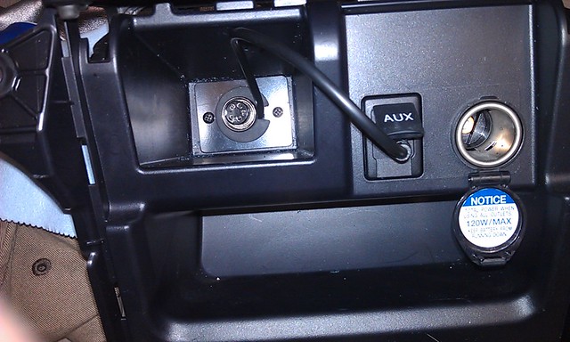
I decided to have the CB connection come out of the cubby hole in the center stack. If you use this location, you will need to order the 4ft microphone extension cable. You don’t need the full 4 feet, but without it you cannot reach from the control box.

PREPPING THE CUBBYHOLE
With the CB kit you get a little plate that allows for the placement of the grommet. The plate is a perfect fit for the back of the cubbyhole.

I taped the back plate to the cubby and used it as a guide to Dremmel the holes.

There is plenty of room in the grommet to run both the CB connector AND the wire for the AUX input to run the audio over the head unit. At first I planned on locking the connector in the grommet, but it turned out to be easier to plug in etc by pulling it further through.

It’s a little fidgety to get the back plate screws in place, but it looks good and works well once done. First the back view; than the front view:

SELECTING AN EXIT LOCATION
I decided to have the CB connection come out of the cubby hole in the center stack. If you use this location, you will need to order the 4ft microphone extension cable. You don’t need the full 4 feet, but without it you cannot reach from the control box.
PREPPING THE CUBBYHOLE
With the CB kit you get a little plate that allows for the placement of the grommet. The plate is a perfect fit for the back of the cubbyhole.
I taped the back plate to the cubby and used it as a guide to Dremmel the holes.
There is plenty of room in the grommet to run both the CB connector AND the wire for the AUX input to run the audio over the head unit. At first I planned on locking the connector in the grommet, but it turned out to be easier to plug in etc by pulling it further through.
It’s a little fidgety to get the back plate screws in place, but it looks good and works well once done. First the back view; than the front view:
Last edited:
Cobra ST 75 CB with 4ft Firestik Antenna (5/7)
ROUTING THE ANTENNA
I used the 6.5ft of cable on the K400 mount to get the antenna coax into the cab. I used the same pass-through as what I used for the roof light wiring. It’s a bit of a slow process to feed the mini UHF connector through the rubber hose, but it was the cleanest/easiest way to route the cable. I then used a 16ft RG316 cable to go from the headliner, via the c pillar down to the door sill. In the center of the front passenger I then went under the carpet to the center tunnel and to the CB control box.

Start by mounting your K400 3/8th mount as low as possible on the rear hatch. I actually bought some shorter set screw because the ones that came with the unit were contacting the paint on the body when the hatch was closed.

I used the included wire guide to bring the 6.5ft lead towards the inside of the hatch.

2 short zip-ties were used to keep the antenna lead in place at the two transfer points between the hatch and the body.

I used the left side connection (same place where I routed the power for the roof lights) to bring the antenna lead into the body. Once inside the body you connect the 16ft antenna extension. I pulled back the C-Pillar trim and followed the rear washer hose to route the antenna extension.

I also did the “hidden storage” mod which gave me easy access to route the antenna extension down and into the door sills.

Use a trim removal tool to pop up the JBL side of the tray and either use force to break off the screw point, or use a small hex screw driver to undo the screws (either way the places where the screws seat into will partially break loose; this is expected.)
Route the antenna extension along the wire-loom that is inside the passenger side door sill.

At this point you will want to pull the trim covering the bolt on the passenger seat off and remove the bolts so you can simply tip the seat backwards and out of the way. You do not have to remove the seat from the vehicle.
There is a piece of velcro’d carpet that you can pull back and easily route the antenna extension under the passenger seat and into the center tunnel. You can see where I made the left-hand turn under the carpet (bottom center) and you can see it coming up in the center tunnel (top center).

Once inside the center tunnel I followed the existing wiring loom again (mainly to use up any slack) and connected the antenna extension to the CB control box.

I used 3M automotive double sides adhesive to secure the CB control box in place.
At this point you are basically done and can start tuning your antenna and putting the car back together.
ROUTING THE ANTENNA
I used the 6.5ft of cable on the K400 mount to get the antenna coax into the cab. I used the same pass-through as what I used for the roof light wiring. It’s a bit of a slow process to feed the mini UHF connector through the rubber hose, but it was the cleanest/easiest way to route the cable. I then used a 16ft RG316 cable to go from the headliner, via the c pillar down to the door sill. In the center of the front passenger I then went under the carpet to the center tunnel and to the CB control box.
Start by mounting your K400 3/8th mount as low as possible on the rear hatch. I actually bought some shorter set screw because the ones that came with the unit were contacting the paint on the body when the hatch was closed.
I used the included wire guide to bring the 6.5ft lead towards the inside of the hatch.
2 short zip-ties were used to keep the antenna lead in place at the two transfer points between the hatch and the body.
I used the left side connection (same place where I routed the power for the roof lights) to bring the antenna lead into the body. Once inside the body you connect the 16ft antenna extension. I pulled back the C-Pillar trim and followed the rear washer hose to route the antenna extension.
I also did the “hidden storage” mod which gave me easy access to route the antenna extension down and into the door sills.
Use a trim removal tool to pop up the JBL side of the tray and either use force to break off the screw point, or use a small hex screw driver to undo the screws (either way the places where the screws seat into will partially break loose; this is expected.)
Route the antenna extension along the wire-loom that is inside the passenger side door sill.
At this point you will want to pull the trim covering the bolt on the passenger seat off and remove the bolts so you can simply tip the seat backwards and out of the way. You do not have to remove the seat from the vehicle.
There is a piece of velcro’d carpet that you can pull back and easily route the antenna extension under the passenger seat and into the center tunnel. You can see where I made the left-hand turn under the carpet (bottom center) and you can see it coming up in the center tunnel (top center).
Once inside the center tunnel I followed the existing wiring loom again (mainly to use up any slack) and connected the antenna extension to the CB control box.
I used 3M automotive double sides adhesive to secure the CB control box in place.
At this point you are basically done and can start tuning your antenna and putting the car back together.
Last edited:
Cobra ST 75 CB with 4ft Firestik Antenna (6/7)
TUNING YOUR ANTENNA (For more information see Firestik Tech Help)
Setting the SWR of Your Antenna© - Firestik® Antenna Company
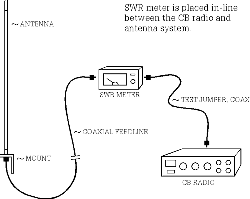
The goal is to have your CB operate at an SWR of 2.0 OR BELOW.
IF SWR IS RED ON ALL CHANNELS – DO NOT OPERATE YOUR CB; YOU WILL RUIN YOUR ELECTRONICS!
SWR below 2.0: Your radio can be operated safely.
SWR above 2.0 but below 3.0: either a bad quality cable, insufficient ground plane or ungrounded antenna mount.
SWR above 3.0: Likely a short in your coax connectors or the mount is installed incorrectly and shorts.
Steps to take an SWR reading:
1) Antenna connected to "ANT" side.
2) Set to “10W”.
3) Set to” FWD”.
4) Turn calibration knob all the way counter clockwise.
5) Turn on your CB.
6) Set your CB to channel 1.
7) Press the "Talk" (key) button and keep the button pressed for the next couple steps.
8) Turn the calibration know until the needle goes all the way over to the far right side and lines up with the "SET" mark.
9) Flip the switch to "REF".
10) Record the reading (the decimal scale is under the main scale).
11) Let go of the "Talk" button.
12) Repeat steps 7 through 11 for channel 19 and channel 40.
Adjusting a LONG antenna:
If the SWR on channel 40 is greater than that on channel 1, your antenna is considered to be "LONG" and reduction of physical height and/or conductor length will correct this situation. Depending upon antenna model, this entails screwing down the tunable tip, or, removing the tip, making short slits in the plastic covering and unwinding and clipping off wire. Firestik Designer Series antennas require loosening the allen screws and lowering the metal whip.
Adjusting a SHORT antenna:
If SWR on channel 1 is greater than that on channel 40, your antenna is considered to be "SHORT" and increasing the physical and/or electrical length of the antenna is required to correct this situation. Because we make our antennas extra long, readings which indicate "Short" normally stem from ground plane deficiency (lack of vehicle metal surface for the antenna to reflect its signal rom). This condition is often corrected by adding a spring and/or quick disconnect to increase the physical height. Ground plane deficiencies can also be compensated for by using dual (co-phased) antennas or special no-ground-plane antenna kits.
Lengthening of the Firestik II and Firefly is accomplished by turning the tuning screw further out. On Firestik and Road Pal models, it requires tip removal, short slits in the plastic covering and, the separation and upward repositioning of three or more wire turns. Firestik Designer Series antennas require loosening the allen screws and raising the metal whip.
NOTE: The shorter the antenna, the more sensitive it is to adjustments. For example, removing two wire turns on a 4 foot antenna might move the SWR by 0.3; the same amount removed from a 2 foot antenna may move the SWR by 1.0. Make smaller adjustments on shorter antennas.
TUNING YOUR ANTENNA (For more information see Firestik Tech Help)
Setting the SWR of Your Antenna© - Firestik® Antenna Company
The goal is to have your CB operate at an SWR of 2.0 OR BELOW.
IF SWR IS RED ON ALL CHANNELS – DO NOT OPERATE YOUR CB; YOU WILL RUIN YOUR ELECTRONICS!
SWR below 2.0: Your radio can be operated safely.
SWR above 2.0 but below 3.0: either a bad quality cable, insufficient ground plane or ungrounded antenna mount.
SWR above 3.0: Likely a short in your coax connectors or the mount is installed incorrectly and shorts.
Steps to take an SWR reading:
1) Antenna connected to "ANT" side.
2) Set to “10W”.
3) Set to” FWD”.
4) Turn calibration knob all the way counter clockwise.
5) Turn on your CB.
6) Set your CB to channel 1.
7) Press the "Talk" (key) button and keep the button pressed for the next couple steps.
8) Turn the calibration know until the needle goes all the way over to the far right side and lines up with the "SET" mark.
9) Flip the switch to "REF".
10) Record the reading (the decimal scale is under the main scale).
11) Let go of the "Talk" button.
12) Repeat steps 7 through 11 for channel 19 and channel 40.
Adjusting a LONG antenna:
If the SWR on channel 40 is greater than that on channel 1, your antenna is considered to be "LONG" and reduction of physical height and/or conductor length will correct this situation. Depending upon antenna model, this entails screwing down the tunable tip, or, removing the tip, making short slits in the plastic covering and unwinding and clipping off wire. Firestik Designer Series antennas require loosening the allen screws and lowering the metal whip.
Adjusting a SHORT antenna:
If SWR on channel 1 is greater than that on channel 40, your antenna is considered to be "SHORT" and increasing the physical and/or electrical length of the antenna is required to correct this situation. Because we make our antennas extra long, readings which indicate "Short" normally stem from ground plane deficiency (lack of vehicle metal surface for the antenna to reflect its signal rom). This condition is often corrected by adding a spring and/or quick disconnect to increase the physical height. Ground plane deficiencies can also be compensated for by using dual (co-phased) antennas or special no-ground-plane antenna kits.
Lengthening of the Firestik II and Firefly is accomplished by turning the tuning screw further out. On Firestik and Road Pal models, it requires tip removal, short slits in the plastic covering and, the separation and upward repositioning of three or more wire turns. Firestik Designer Series antennas require loosening the allen screws and raising the metal whip.
NOTE: The shorter the antenna, the more sensitive it is to adjustments. For example, removing two wire turns on a 4 foot antenna might move the SWR by 0.3; the same amount removed from a 2 foot antenna may move the SWR by 1.0. Make smaller adjustments on shorter antennas.
Last edited:
Cobra ST 75 CB with 4ft Firestik Antenna (7/7)
HAND HELD CONTROLLER MOUNT
Not a whole lot to say here; the pictures pretty much speak for themselves.
Back view; one untrimmed screw.

Side View:

Front view on trim:

I had to trim a little bit of the plastic from the cubbyhole, but my knife made short and easy work of that.

Installation complete:

HAND HELD CONTROLLER MOUNT
Not a whole lot to say here; the pictures pretty much speak for themselves.
Back view; one untrimmed screw.
Side View:
Front view on trim:
I had to trim a little bit of the plastic from the cubbyhole, but my knife made short and easy work of that.
Installation complete:
Last edited:

MeBe4running
New member
place holder for CB hand held mount
WOW, you have been busy! I cut my hand just like you have done down there as well. Dam theres some sharp pieces back there! Nice work on the CB install, might steal a few ideas there! Keep up the good work!
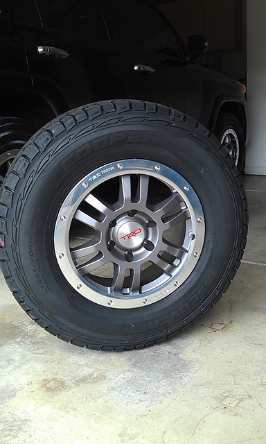
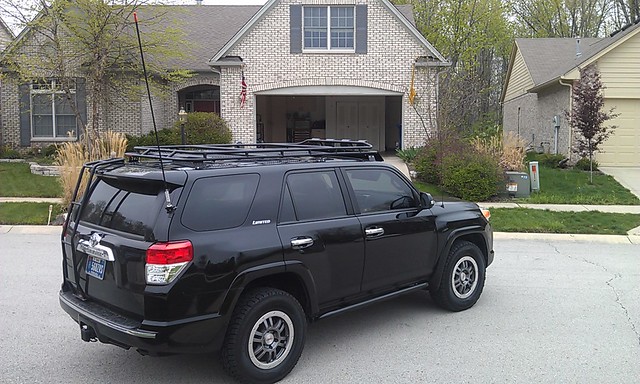
TRD Rims and Cooper Tire Discoverer ATP LT265/70R17
17INCH RIMS & TIRES
TRD forged 17" rims (PTR45-35010) $1,650.00 5 rims toyotatrdpart.com
Wheel Installation Kit 12mm Conical (PTR27-89100) $150.00 toyotatrdpart.com
Shipping $60.00 toyotatrdpart.com
Cooper Tire Discoverer ATP $1,343.53 Discount Tire
Sold OEM rims and tires $(1,175.00) [Private sale]
Total $2,028.53
RIMS:
17' TRD Forged Wheel with BeadLock Ring (PTR45-35010)
TRD 17 inch x 7.5 inch x 6 mm FORGED Aluminum Off-Road Wheel with Bead Lock Styling. 6 on 139.7mm P.C.D. 106 mm Center Bore.
Uses 12mm TRD Spline-Drive Conical-Seat Lug Nut Kit (PTR27-89100) included for PPO, recommended and sold separately for DIO.
Tires are OE P265/70R17 113S M + S This wheel is conflicted with the Limited models with 20 inch OE wheels due to 20 inch door jamb tire pressure label.
PPO Code: L2 PPO Time: 1.63 hrs TRD wheel "LONG" lugnut installation kit, PTR27-89100 is included for PPO (required and sold separately for DIO).
This kit comes with 20 Spline-Drive Conical-Seat 12mm Lug Nuts with captured conical swivel washers, 1 "LONG" Spline Drive Tool, 4 TRD Wheel Locks with TRD logo laser-etched on top of each Lock, and 1 TRD "LONG" Wheel Lock Tool. 21mm wrench flat.
All TRD Wheels are designed for use with 20 degree OE wheel sensors and fit kits. 20 degree sensors are already on OE Alloy wheels.
Refer to your parts department and or the installation instructions for proper TPMS part number required for your particular application.
Backed by Toyota's 3-year/36,000-mile New Vehicle Limited Warranty, valid at any Toyota dealership nationwide.
[per http://www.toyotatrdparts.com/scripts/prodView.asp?idproduct=-118]
Current Pressure: 40PSI
Torque Specs: 82ft/lbs (112N-m) - Do NOT use an Impact Gun. Air ratchets are OK.
Tire Details:
121/118S
Load Range: E
LT265/70 R17
The P265/70R17 load range B carries 2679# at a maximum inflation of 44psi.
The LT265/70R17 load range E carries 3195# at 80psi.
The P285/70R17 load range B carries 2833# at 44psi.
The LT285/70R17 load range E carries 3195# at 80psi.
The actual weights of each tire are:
P265/70R17=41Lbs,
LT265/70R17=50Lbs,
P285/70R17=45Lbs, and the
LT285/70R17=55Lbs.
Specs:
1 ply nylon
2 plies steel
2 plies polyester
Sidewall:
2 plies polyester
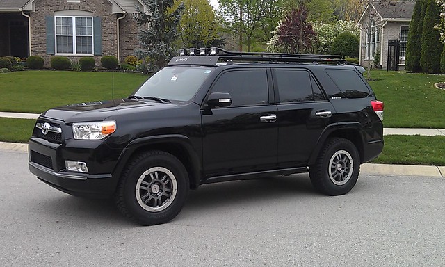
17INCH RIMS & TIRES
TRD forged 17" rims (PTR45-35010) $1,650.00 5 rims toyotatrdpart.com
Wheel Installation Kit 12mm Conical (PTR27-89100) $150.00 toyotatrdpart.com
Shipping $60.00 toyotatrdpart.com
Cooper Tire Discoverer ATP $1,343.53 Discount Tire
Sold OEM rims and tires $(1,175.00) [Private sale]
Total $2,028.53
RIMS:
17' TRD Forged Wheel with BeadLock Ring (PTR45-35010)
TRD 17 inch x 7.5 inch x 6 mm FORGED Aluminum Off-Road Wheel with Bead Lock Styling. 6 on 139.7mm P.C.D. 106 mm Center Bore.
Uses 12mm TRD Spline-Drive Conical-Seat Lug Nut Kit (PTR27-89100) included for PPO, recommended and sold separately for DIO.
Tires are OE P265/70R17 113S M + S This wheel is conflicted with the Limited models with 20 inch OE wheels due to 20 inch door jamb tire pressure label.
PPO Code: L2 PPO Time: 1.63 hrs TRD wheel "LONG" lugnut installation kit, PTR27-89100 is included for PPO (required and sold separately for DIO).
This kit comes with 20 Spline-Drive Conical-Seat 12mm Lug Nuts with captured conical swivel washers, 1 "LONG" Spline Drive Tool, 4 TRD Wheel Locks with TRD logo laser-etched on top of each Lock, and 1 TRD "LONG" Wheel Lock Tool. 21mm wrench flat.
All TRD Wheels are designed for use with 20 degree OE wheel sensors and fit kits. 20 degree sensors are already on OE Alloy wheels.
Refer to your parts department and or the installation instructions for proper TPMS part number required for your particular application.
Backed by Toyota's 3-year/36,000-mile New Vehicle Limited Warranty, valid at any Toyota dealership nationwide.
[per http://www.toyotatrdparts.com/scripts/prodView.asp?idproduct=-118]
Current Pressure: 40PSI
Torque Specs: 82ft/lbs (112N-m) - Do NOT use an Impact Gun. Air ratchets are OK.
Tire Details:
121/118S
Load Range: E
LT265/70 R17
The P265/70R17 load range B carries 2679# at a maximum inflation of 44psi.
The LT265/70R17 load range E carries 3195# at 80psi.
The P285/70R17 load range B carries 2833# at 44psi.
The LT285/70R17 load range E carries 3195# at 80psi.
The actual weights of each tire are:
P265/70R17=41Lbs,
LT265/70R17=50Lbs,
P285/70R17=45Lbs, and the
LT285/70R17=55Lbs.
Specs:
1 ply nylon
2 plies steel
2 plies polyester
Sidewall:
2 plies polyester
Last edited:

ColoradoFrosty
New member
Dang Okki... nice work! The CB install looks great and your detailed documentation is awesome. Thanks for taking the time to share!
Dang Okki... nice work! The CB install looks great and your detailed documentation is awesome. Thanks for taking the time to share!
No Problem.. Glad to help to keep the community educated
Okki
DannyLlama
Elite Member
Nice wheel's!
Suites your car spot on, I think it would look weird on a Pearl limited though .
.
Plus it's too "rugged" for the wifey..
Suites your car spot on, I think it would look weird on a Pearl limited though
.Plus it's too "rugged" for the wifey..
Similar threads

- Replies
- 2
- Views
- 2K
- Replies
- 1
- Views
- 3K

- Replies
- 9
- Views
- 3K
- Replies
- 1
- Views
- 2K


