Only KDSS w/lift need apply

That’s all I can think anytime I see posts about disabling or removing it. Why would you spend an extra $1,800 when it’s much easier to find a 4Runner without KDSS than with it.

However, reading posts by adults who don’t know basic grammar and the difference between there, their, and they’re is much worse.


Because a kdss 4runner that can be controlled is a better 4runner then non kdss 4runner. It’s more versatile. Guarantee you Toyota didn’t give the option to control that so they wouldn’t be liable for accidents. Same reason why jeep doesn’t allow the sway bar to discounnect after a certain speed.

Another reason why one would spend 1800 extra is because it’s America and we can do whatever the f we want with our own money.

This is a forum. Not to many ppl care about basic grammar unless you were on the boob too long. [emoji2371].


Sent from my iPhone using Tapatalk
 
Last edited:
The point is not to completely disable KDSS from the system, but rather give the driver the ability to choose when it is on or off if needed. There are times when you're going over the KDSS-setpoint while cruising offroad and you don't want the harsh ride that it produces. Being able to flip a switch and turn it off temporarily until you hit pavement, etc, seems like a totally reasonable thing to want to do in my opinion.
 
I really don't understand everyone's issues with this. Who cares if you bought a kdss equipped vehicle and want the ability to turn it off whenever. I agree it is better to have it when you want it, and have the ability to turn it off whenever, then to not have it at all.

As for Dom being a freeloader, I would say that's a little harsh. Are the prints out there to the rest of us? Sure. Are they exactly the same as he used to build his harness? Maybe, maybe not. Either way, does it really matter? No one is forcing anyone to buy the harness. It's anyone's choice to do so.

Personally, I would prefer to buy from someone who's tested and put in the work. Electrical, how simple or not is not my forte, and i'm pretty mechanically inclined. At the end of the day, its no different than someone who puts anything on their vehicle, some may not like it, but to each their own. He's not forcing anyone to buy anything, but simply giving the option if that's the route you want to go.

If you don't like it, don't comment. Forums are great as some mentioned to share idea's and your not wrong. I guess it depends on how you look at it, because technically Dom is sharing his idea...
 
I really don't understand everyone's issues with this. Who cares if you bought a kdss equipped vehicle and want the ability to turn it off whenever. I agree it is better to have it when you want it, and have the ability to turn it off whenever, then to not have it at all.

As for Dom being a freeloader, I would say that's a little harsh. Are the prints out there to the rest of us? Sure. Are they exactly the same as he used to build his harness? Maybe, maybe not. Either way, does it really matter? No one is forcing anyone to buy the harness. It's anyone's choice to do so.

Personally, I would prefer to buy from someone who's tested and put in the work. Electrical, how simple or not is not my forte, and i'm pretty mechanically inclined. At the end of the day, its no different than someone who puts anything on their vehicle, some may not like it, but to each their own. He's not forcing anyone to buy anything, but simply giving the option if that's the route you want to go.

If you don't like it, don't comment. Forums are great as some mentioned to share idea's and your not wrong. I guess it depends on how you look at it, because technically Dom is sharing his idea...


It’s just haters is all. Also this is not my idea at all. I just been doing sway bar disconnects since jeep offered sway bar disconnect via button. We’ve been doing in that world since day one. So same time when I found out about kdss.


Sent from my iPhone using Tapatalk
 
I really don't understand everyone's issues with this. Who cares if you bought a kdss equipped vehicle and want the ability to turn it off whenever. I agree it is better to have it when you want it, and have the ability to turn it off whenever, then to not have it at all.

As for Dom being a freeloader, I would say that's a little harsh. Are the prints out there to the rest of us? Sure. Are they exactly the same as he used to build his harness? Maybe, maybe not. Either way, does it really matter? No one is forcing anyone to buy the harness. It's anyone's choice to do so.

Personally, I would prefer to buy from someone who's tested and put in the work. Electrical, how simple or not is not my forte, and i'm pretty mechanically inclined. At the end of the day, its no different than someone who puts anything on their vehicle, some may not like it, but to each their own. He's not forcing anyone to buy anything, but simply giving the option if that's the route you want to go.

If you don't like it, don't comment. Forums are great as some mentioned to share idea's and your not wrong. I guess it depends on how you look at it, because technically Dom is sharing his idea...

The issue isn't the selling of a pre-packaged solution. It's great for folks who can't or don't want to put it together themselves.

It's the, "I'm not going to tell you what wires to interrupt" response that's the issue. Taking the position of refusal to share what he learned is a problem. And it's a particularly odd response given that it's literally in a thread created by someone else who already told him and everyone else how to do it. And there's a dozen people who are happy to read the wiring diagram for him or anyone else if they don't know how. And even design a paint by numbers type wiring guide. There's dozens of them on this forum for all sorts of functions. The freeloader problem is making use of the collective forum knowledge but refusing to contribute back. Going to the length of trying to hide a simple circuit by using all black wires in the harness and making a connection in the loom is both a stupid idea and a demonstration of the freeloader mentality.
 
The issue isn't the selling of a pre-packaged solution. It's great for folks who can't or don't want to put it together themselves.

It's the, "I'm not going to tell you what wires to interrupt" response that's the issue. Taking the position of refusal to share what he learned is a problem. And it's a particularly odd response given that it's literally in a thread created by someone else who already told him and everyone else how to do it. And there's a dozen people who are happy to read the wiring diagram for him or anyone else if they don't know how. And even design a paint by numbers type wiring guide. There's dozens of them on this forum for all sorts of functions. The freeloader problem is making use of the collective forum knowledge but refusing to contribute back. Going to the length of trying to hide a simple circuit by using all black wires in the harness and making a connection in the loom is both a stupid idea and a demonstration of the freeloader mentality.


You still have no idea how I did it. The whole hiding the wire thing is for the consumer or some1 wanting to buy it to reverse engineer it. Regardless of what I do, they will be able to figure it out anyway. I’m just making it a little harder to do that. But if you read closely on my responses to you, you would know by now which wire.

Also yes making a connection in the loom is way stupid. That’s exactly what I didn’t do.

Stop guessing / assuming and just go do it already. Do your version of it or mine or whatever. Just do something other then I know it all smart ass engineer brain tactics [emoji2359][emoji2359][emoji2359] . This thread has been here to f’n long with no answer or real results as far as the actual switch. Only disconnecting it. I don’t find the answer here or in the forum. I found out which wire from my testing.


Sent from my iPhone using Tapatalk
 
Last edited:
Jetboy: Please stop fueling an argument.

The product will not be for sale via this forum and for people like me that understand the flexibility this will provide it is invaluable.

I firmly believe the statement “it’s a secret” was in jest, it doesn’t matter one bit. For the grammar warriors of the forum now you can pick me apart, is it proper to use “jest” in this context?
 
The issue isn't the selling of a pre-packaged solution. It's great for folks who can't or don't want to put it together themselves.

It's the, "I'm not going to tell you what wires to interrupt" response that's the issue. Taking the position of refusal to share what he learned is a problem. And it's a particularly odd response given that it's literally in a thread created by someone else who already told him and everyone else how to do it. And there's a dozen people who are happy to read the wiring diagram for him or anyone else if they don't know how. And even design a paint by numbers type wiring guide. There's dozens of them on this forum for all sorts of functions. The freeloader problem is making use of the collective forum knowledge but refusing to contribute back. Going to the length of trying to hide a simple circuit by using all black wires in the harness and making a connection in the loom is both a stupid idea and a demonstration of the freeloader mentality.

haven't you said how easy it is and how many others have done the same? so is he even hiding anything at that point? sure maybe he used a different process, who cares. Don't get so hung up on one member's desire to create a new product for the market. if there is a demand it will work out, if not, he will have wasted time and money and everyone can "say see i told you so".
 
I've had a few PM's about how to do this. So...let's add some tech here. Rather than an electrical diagram - I drew an easy guide for DIY folks who might not be familiar with a wiring diagram. Typical wiring diagrams are like greek if you're not familiar with them. And having more of a plainly drawn out version might be more helpful. So I thought I'd take my own advice on contributing a bit more and draw this in paint rather than SkyCAD which is what i was going to do.

The first picture is the correct way to wire this using Bosch style relays. Lots of relay options. These are the most common, cheap, and waterproof. Personally I prefer to use relay PCBs with solid state relays. But this is the easiest way with parts that most people are familiar with. The numbering system on the relay pins is important. They are not universal in color on the pigtails, but the pin numbering is universal so you can rely on the pin number matching whatever brand of relay. I would use waterproof relays and mount them in a small box on the frame rail next to the KDSS Accumulator. You will run a single wire up to the dash from the KDSS accumulator. The wiring colors are not meaningful in my drawing. The two OEM wires you will interrupt with the relay are pins 5 and 6. On the OEM harness they will be light green and pink. On the bypass harness you would make - who knows. Some will come with randomly colored wires. Some will come all black. Doesn't really matter. Just make sure that the brown and yellow wires on my drawing match up to the pink and light green ones on the factory wiring and that they go to pins 30 and 87a on the two relays.

If you do not use resistors - leave pin 87 open on each relay. Do not connect to ground or you'll create a short circuit that will blow the fuse.

The connectors are available either as DIY assembly where you crimp your own insulation displacement terminals (requires a special tool - not expensive, but you can't do this with pliers very well). Or they are available with pigtails where you'd use butt connectors. The assembly-required pair of connectors is roughly $5-10 for a pair. The pigtail set is around $25-30 for a pair. Relays are $5 each. Resistors are $5 for a lifetime supply of them.

The two resistors are not required if you want to let the dash light come on. They are there to replace the resistance of the solenoid in the shutter valve and mimic the resistance so the dash light will not come on. I have not measured the internal resistance of the solenoid when activated. I would start with a 1k ohms just as a base point. Typically 12v solenoids are around 100 ohms, but I'd start higher and see how it works. Higher resistance = less current and less parasitic watts wasted. Or measure the resistance between pin 4 and 5 on the male plug end on the accumulator and choose something a little bit higher. I don't know exactly how Toyota's ECU measures the continuity through the shutter valve.

The second image is the shade tree mechanic version. There's a lot of reasons not to do it this way. But it would probably work... at least initially until it doesn't. It's the easiest way to do it. The primary failure mode on this style is open valves. That's the opposite of sound engineering. Failure modes should revert to OEM function. The first diagram does this.

Another way to do this entirely under the dash is to interrupt the same pink and light green wires from the KDSS ECU under the dash. Then follow the same wiring as the first image below where those wires would be represented by the brown and yellow wires. You'd need to find a place to stick the relays under the dash. But it might be easier and you wouldn't have to buy any connector housings, but you would cut in to the factory wires to put relays on them.

Good luck.
 

Attachments

  • KDSS Shutter Valve Manual Overide 1 - Copy.jpg
    KDSS Shutter Valve Manual Overide 1 - Copy.jpg
    114.8 KB · Views: 3,121
  • KDSS Shutter Valve Manual Overide BASIC - Copy.jpg
    KDSS Shutter Valve Manual Overide BASIC - Copy.jpg
    105.1 KB · Views: 2,196
Last edited:
I've had a few PM's about how to do this. So...let's add some tech here. Rather than an electrical diagram - I drew an easy guide for DIY folks who might not be familiar with a wiring diagram. Typical wiring diagrams are like greek if you're not familiar with them. And having more of a plainly drawn out version might be more helpful. So I thought I'd take my own advice on contributing a bit more and draw this in paint rather than SkyCAD which is what i was going to do.

The first picture is the correct way to wire this using Bosch style relays. Lots of relay options. These are the most common, cheap, and waterproof. Personally I prefer to use relay PCBs with solid state relays. But this is the easiest way with parts that most people are familiar with. The numbering system on the relay pins is important. They are not universal in color on the pigtails, but the pin numbering is universal so you can rely on the pin number matching whatever brand of relay. I would use waterproof relays and mount them in a small box on the frame rail next to the KDSS Accumulator. You will run a single wire up to the dash from the KDSS accumulator. The wiring colors are not meaningful in my drawing. The two OEM wires you will interrupt with the relay are pins 5 and 6. On the OEM harness they will be light green and pink. On the bypass harness you would make - who knows. Some will come with randomly colored wires. Some will come all black. Doesn't really matter. Just make sure that the brown and yellow wires on my drawing match up to the pink and light green ones on the factory wiring and that they go to pins 30 and 87a on the two relays.

If you do not use resistors - leave pin 87 open on each relay. Do not connect to ground or you'll create a short circuit that will blow the fuse.

The connectors are available either as DIY assembly where you crimp your own insulation displacement terminals (requires a special tool - not expensive, but you can't do this with pliers very well). Or they are available with pigtails where you'd use butt connectors. The assembly-required pair of connectors is roughly $5-10 for a pair. The pigtail set is around $25-30 for a pair. Relays are $5 each. Resistors are $5 for a lifetime supply of them.

The two resistors are not required if you want to let the dash light come on. They are there to replace the resistance of the solenoid in the shutter valve and mimic the resistance so the dash light will not come on. I have not measured the internal resistance of the solenoid when activated. I would start with a 1k ohms just as a base point. Typically 12v solenoids are around 100 ohms, but I'd start higher and see how it works. Higher resistance = less current and less parasitic watts wasted. Or measure the resistance between pin 4 and 5 on the male plug end on the accumulator and choose something a little bit higher. I don't know exactly how Toyota's ECU measures the continuity through the shutter valve.

The second image is the shade tree mechanic version. There's a lot of reasons not to do it this way. But it would probably work... at least initially until it doesn't. It's the easiest way to do it. The primary failure mode on this style is open valves. That's the opposite of sound engineering. Failure modes should revert to OEM function. The first diagram does this.

Another way to do this entirely under the dash is to interrupt the same pink and light green wires from the KDSS ECU under the dash. Then follow the same wiring as the first image below where those wires would be represented by the brown and yellow wires. You'd need to find a place to stick the relays under the dash. But it might be easier and you wouldn't have to buy any connector housings, but you would cut in to the factory wires to put relays on them.

Good luck.


Yeah definitely I’d prefer pcb’s with solid state relays over standard relays.

JetBoy, curious if you have actually done the wiring or just going off some one who did or just going off diagram? I’d prefer to not use those resistors so that kdss light will come on as an indicator rather then using a switch to tell me its deactivated or not. The problem with that is , when you interrupt those circuits , and with out resistors is that the kdss light will come on after you interrupt but will stay on when connecting them again and will not turn off until you cycle your key. I don’t know if the kdss system is open or closed because I didn’t like that test result so I didn’t do the seat of the pants feel by driving until I was able to achieve the same results with the kdss light coming on as when unplugging the system.

What would be the reason for the light to stay on and not go away till you cycle the key? Clearly you are a lot more knowledgeable then me about all this. Seriously.

I also agree with the way pic 2 is wired , is the low budget cheap way to do it and will work until it doesn’t and like you mention , you do want the failure modes to fail into stock oem configurations with the system closed.


Sent from my iPhone using Tapatalk
 
Last edited:
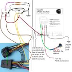
I have not done this to my 4Runner. I probably won't. I don't know how long the metal baffles in the accumulator will live being open like this. Flexing metalic baffles at high speed doesn't give me warm fuzzy feelings about them also having a long service life. The LC200 is sort of always "open" but not really. It uses ball style check valves so it closes the accumulators at higher fluid flows, it just does it automatically via a mechanical check valve instead of with electronics. The LX570 uses similar designed high pressure accumulators in the AHC system, but they also are on and off depending on a variety of factors. The LX system uses rubber bladders in some, metal baffles in some, and floating pistons in other chambers. I wish I knew more about why they used each one. The metal baffles are generally for pressures too high for bladders or pistons to maintain the seal between the nitrogen and hydraulic fluids. They seem to last a long time in that system, but I don't know how much they cycle.

Without seeing the ECU code (I think it's encrypted) I don't know why the light stays on. From the FSM the ECU tests the relays periodically. I don't know how often. It believe it is effectively testing resistance in the circuits. According to the FSM if it senses a short circuit in either channel - it will test 8 times and then disconnect the circuit and illuminate the warning light. Probably until the next time you turn it on. It doesn't say how long this lasts, why it does it 8 times, or how it's actually testing the circuit for continuity and resistance. It also doesn't tell us when this happens or how often.

If the circuit is open - broken wire or failed coil in the solenoid that moves the valve - it will register a high resistance and then illuminate the dash light. It certainly knows whenever the circuit is open. Even if when the system isn't sending power to the shutter valves. So it's either testing all the time, on a clock with routine checks, or based on some other outside trigger from the canbus. I'm not an expert on the clocking of the various ECUs or what the communication looks like between them. I've read that the newer Toyota models have a fairly complex handshake between all the ECUs and there may be a lot more info back and forth than I think. My guess would be that there's basically a few or whether a shared clock is used. If I have some more time I'll try to look more closely at the wiring and see if something is obvious.

My guess - and this is pure speculation - is that the KDSS ECU will store a code and not reset the error code until the next time the ignition switch is cycled off and back on. It's possible that the ECU only uses short term memory and doesn't store the error codes long term, but that seems unlikely. My guess is that it just re-tests on startup and clears all the error codes, but that you can't reset it without restarting.
 
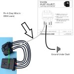
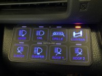
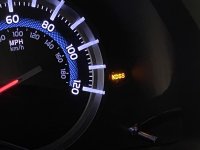
So..... I got a prototype Switch from [MENTION=433255]dom42[/MENTION] and let me tell you.... This is a HUGE game Changer! This, coupled with the spacers that blackgatecustoms also sells, it is a whole next level! With the system switched off (KDSS light on), the Pistons are relaxed and the 4runner takes the bumps and turns it very plush! Im very happy with it and cant wait for it to be released to the public! THis is a huge win for us KDSS folks! People are going to want to put it back in, or buy their truck brand new with the KDSS.
 
Couple pics
 

Attachments

  • 36A8CFD8-4206-4177-BEF9-071CCCF99DC5.jpeg
    36A8CFD8-4206-4177-BEF9-071CCCF99DC5.jpeg
    100.2 KB · Views: 1,646
  • 59AD1AF6-210A-4F3B-91F9-9FD394E008AE.jpg
    59AD1AF6-210A-4F3B-91F9-9FD394E008AE.jpg
    128.8 KB · Views: 1,856
I definitely need this switch haha, any updates? [MENTION=433255]dom42[/MENTION]


About 2 months out. I’m having a professional wireharness manufacturer put them together for me. They have the blue prints and the sample harness. They are just making it in their most professional way possible. All the way down to certifications on the crimp and all. USA made stuff. Only thing not USA made is the factory connector which we sourced over seas direct from manufacture where Toyota gets them.


Sent from my iPhone using Tapatalk
 
About 2 months out. I’m having a professional wireharness manufacturer put them together for me. They have the blue prints and the sample harness. They are just making it in their most professional way possible. All the way down to certifications on the crimp and all. USA made stuff. Only thing not USA made is the factory connector which we sourced over seas direct from manufacture where Toyota gets them.


Sent from my iPhone using Tapatalk

Looking forward to the KDSS switch!
 

Members online

Forum statistics

Threads
278,315
Messages
3,554,104
Members
248,016
Latest member
Advally Service

Trending content

Back
Top