Opt7 leds

I have the same lights, harness, and switch.

Looks like I need to hack up the opt7 harness a bit by chopping off the switch that comes with it and then connecting the AOB switch. Will be looking for an unused plug under the dash for the gray wire connection to illuminate the switch.


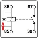
In looking at the opt7 harness and figuring out how to use the AOB switch instead of the supplied one, it looks like the relay connection is backwards...pin 86 is connected to battery neg, while the blue switched hot goes to 85.

If it doesn't matter that the 85/86 can be backwards, it looks I connect as follows:

AOB green - opt7 white

AOB red - opt7 blue

AOB black - opt7 black

AOB blue - to auto illumination circuit grey
 
In looking at the opt7 harness and figuring out how to use the AOB switch instead of the supplied one, it looks like the relay connection is backwards...pin 86 is connected to battery neg, while the blue switched hot goes to 85.

If it doesn't matter that the 85/86 can be backwards, it looks I connect as follows:

AOB green - opt7 white

AOB red - opt7 blue

AOB black - opt7 black

AOB blue - to auto illumination circuit grey

Hi cheeser,

No it doesn't matter whether you connect #85 or #86 to GND or HOT to trigger your relay coil. As long you remember that #30 and #87 are N/O (normally open) contacts, and #30 and #87A are N/C (normally closed) contacts you should be fine!

Cheers!
 
Hey [MENTION=83083]rigtec[/MENTION],

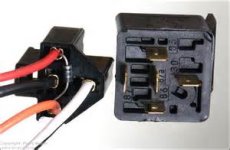
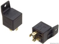
My 2 cents on the diode question, will a non diode relay work perfectly fine, absolutely. But, with modern automotive electronics, I prefer to use relays that incorporate a internal diode to prevent voltage spikes when relay disengages (turns off).
relay.jpg thF8AYCNFV.jpg

Relays without diodes you can A) solder diode to terminals on relay, or B) add diode to harness...........

harness diode.jpg

I prefer internal opposed to external method because of corrosion issues.

Keep up the great work buddy!
 

Attachments

  • relay.jpg
    relay.jpg
    13.2 KB · Views: 835
  • harness diode.jpg
    harness diode.jpg
    9.6 KB · Views: 813
  • thF8AYCNFV.jpg
    thF8AYCNFV.jpg
    13.3 KB · Views: 734
Last edited:
I am curious as to why opt7 wired their relay backwards across 85/86?

I assume I could easily switch them (small pick for the retainer). I don't think they used a diode based relay, but that could be easily switched as well after switching inputs.
 
Hey [MENTION=83083]rigtec[/MENTION],

My 2 cents on the diode question, will a non diode relay work perfectly fine, absolutely. But, with modern automotive electronics, I prefer to use relays that incorporate a internal diode to prevent voltage spikes when relay disengages (turns off). ...I prefer internal opposed to external method because of corrosion issues.

Keep up the great work buddy!

See... this is what i love about this forum, I learn something new here everyday, Thanks Barry!

...and of course Best to you!
 
In looking at the opt7 harness and figuring out how to use the AOB switch instead of the supplied one, it looks like the relay connection is backwards...pin 86 is connected to battery neg, while the blue switched hot goes to 85.

If it doesn't matter that the 85/86 can be backwards, it looks I connect as follows:

AOB green - opt7 white

AOB red - opt7 blue

AOB black - opt7 black

AOB blue - to auto illumination circuit grey
I followed the above AOB to Opt7 harness wiring combination. The AOB switch illumination stays on even with the key out. Did you have the same result and how did you fix it? TIA
 

Members online

Forum statistics

Threads
278,309
Messages
3,554,066
Members
248,016
Latest member
Advally Service

Trending content

Back
Top