OSRAM LEDFOG101 to be installed in 2012 SR5

RysiuM

New member
OSRAM LEDFOG101 installed in 2012 SR5

So looking for Euro-friendly Daytime Running Lights for 2012 4Runner I decided to get Osram LEDFOG101 lights. They are quite pricey here in US, so I ordered the box from Amazon UK. I have also ordered Toyota-Specific brackets for easy mounting. The price on Amazon UK was 200 GBP for lights and 40 GBP for brackets but the price it was including VAT (Tax for UK). Shipping to US excluded VAT so the total price dropped for me by almost 25%. Including shipping, exchange rate and other fees Amazon charged me the out the door price was $376.89.

The box arrived in 5 days (including weekend) in perfect condition with all goodies inside:

4runner-fogdrl-01.jpg


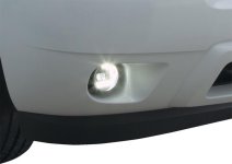
The quality of lamps and brackets was superb. The design of LEDFOG101 is also clever. Each lamp has L-shape Daytime Running Lights and center reflector for Fog light.

4runner-fogdrl-02.jpg


It is certified for Europe and USA (all required markings are imprinted on lenses)

4runner-fogdrl-03.jpg


The LED itself is 7W for fog light and 10W for DRL in each lamp.

4runner-fogdrl-04.jpg


Each lamp is connected to driver-controller which is a little oversized as the label says it can handle total 16W for fog lights and 25W for DRL.

4runner-fogdrl-05.jpg


The controller is not just a LED driver but also has some logic switching each light function based on the combination of signals on the input wires. It is designed in mind of having automatic DRL turn on when you start the car and turn off as soon as you turn on the marker or driving lights (European requirements)

4runner-fogdrl-06.jpg


But lucky me, 2012 4Runner (at least SR5 model) has DRL switch so I'm going to wire the controller a little bit different. I wanted to utilize the logic programmed in the main body ECU for controlling DRL which takes not only the position of DRL switch but also checks if engine is running, parking is brake released etc...

Yesterday night I emailed Osram support with questions if the controller will behave the way I wanted when I wire it my own way. Osram emailed me back this morning with confirmation that it will work, so I'm good to go.

I don't know if I will wire the controller to blinkers for feature "see where you turn" - first I will have to disable original factory DRL in front blinkers for that.

My plan is to connect the "ignition wire" from the controller to body ECU where DRL signal is connected with flasher's DRL input.

Now I need your :help: with 2012 4Runner wiring

Based on 2010 FMS diagram, there is a wire wire going from Main Body ECU to the flasher unit and then connecting it to the new DRL relay (see diagram below).
1. How does this part of diagram looks for 2012 4Runner (for example on Mitchell's manuals)?
2. What is the connector number for each wire?
3. Which connectors?
4. What is the signal level on the Main Body ECU DRL output? Is it +12 V when active and 0V when not?

My flasher is on the left side of the dash, not on the right as in 2010 model.

4runner-fogdrl-07.jpg
 
Last edited:
Register to hide this ad
Last edited:
Are these the exact same thing for less $?

Yes/No/Maybe :pray2:

Sylvania is the Osram's brand name for USA, so basically it is the same company but because it is branded for USA market, Osram's products sold under the Sylvania brand may be different. Probably the major difference is certification. Even if DRL-FOG.WEB (Sylvania) is the same product as as LEDFOG101 (Osram) it may be certified only for USA (DOT).

I checked this item on Sylvania page, and either it is different item or they have the photo screwed up as it looks like it shows the car with the left fog light on the right fender. :tape2:

Other than that from the pictures it looks like very similar lamp. Can't say.
 

Attachments

  • SylvaniaLED.jpg
    SylvaniaLED.jpg
    32.3 KB · Views: 3,690
Yeah, I wasn't sure either. Not many specifications really listed on the Osram Sylvania site, unfortunately. Makes it really difficult to truly know what you're getting.
 
Not many specifications really listed on the Osram Sylvania site, unfortunately. Makes it really difficult to truly know what you're getting.

I was searching Internet for pictures, articles and videos looking for the marking on lenses which would show what certifications they have. Of course you can't trust "E-bay shipped from China" because they write on lenses anything they want without going through certification process. But you can trust brand names as it would be a suicide for them to print marks for certification they don't have. Finally I saw some video of the guy showing LEDFOG101 where I noticed required markings. That made me spend extra 100 bucks for Osram over Silvania.

Now returning to my questions:
1. In 2012 4Runner is there a wire wire going from Main Body ECU to the flasher unit and then connecting it to the new DRL relay? Can anyone with Mitchell's or TIS subscription confirm that?
2. What is the connector number for each wire?
3. Which connectors (and locations)?
4. What is the signal level on the Main Body ECU DRL output? Is it +12 V when active and 0V when not (actually if I know where is the wire I can measure it myself)?

I'm stick without that info. I was going to get TIS subscription - it's fine service but hell is expensive. Michell is easier on the wallet but I'm not sure if I would be able to get what I want.

Please, anyone?
 
Please, anyone?

Really, 30 thousand active members on the forum and nobody does electricity :smashputer: If I don't know these answers I will not be able to install these lights, then you will never know :naughty:

I bench-tested lights checking all non-documented combinations of input signal and looking what the output is. There are few conclusions:

1. None of the "input" wires carry significant current. The whole power to LEDs goes via red (fused) wire connected to the battery +12V and the black wire connected to ground.

2. There is no input combination that will turn on both LEDs (Fog and DRL lights together), It is either Fog or DRL or none

3. DRL lights take 2.5A (both) from the battery. They are very bright and blinding. It would be criminal to use them on the street at night.

4. Fog lights take 1.5A (both) from the battery. They project quite narrow beam with visible cut-off line. I'm not sure if the cut-off is the best on the market (I think projector headlights in my Mazda had better cut-out) but for sure it is much better than factory 4Runner fog lights.

For my purpose I found that it is doable to achieve the result I wanted, which is replicating factory DRL function (on the switch).

The connection would be:
1 (red) = battery +12 or somewhere in the fuse box where +12V high Amp is available after the ignition is turned on (I need to find such point and Edit: It would be pin 10 or 56 in 2C connector in Master Body ECU with new fuse added to the empty slot in the fuse box. EDIT2: 2C is difficult to access, I used 2D plug pin 8 and fuse between KDSS and TOWING BKUP. )
2 (black), 4 (brown) = ground
5 (blue) = DRL output from ECU (EDIT: It will not work as DRL output from ECU is zero when active - it need some signal reverser. EDIT2: Finally simply connected with red wire (1) so DRL are always on when Ignition is ON and marker lights are off ignoring the factory DRL switch position.)
6 (white), 7 (green), 8 (gray) = not connected
9/10 (yellow/black) = to one of Fog lamp connector (yellow must be +12V when active.). (EDIT: Polarity of 4Runner plug was opposite to OSRAM plug. I swapped wires in Osram plug to mach my 4Runner Folg Light plug.)

For "Euro mode" (DRL must be off when parking lights are on):
6 (white) = marker light or any other place that will have +12V when parking lights are turned on. (EDIT: Because I abaondened idea of using DRL signal from ECU I connected this wire with "Tail lamp" signal which was on pin 15 in 2D connector (in ECU).)

Note: The blinker option (turning one Fog LED when blinker is flashing) described on original schematic will only work if DRL lights are off so it will work when the device is connected exactly like in the original diagram: One Fog will turn on only when the wire 5 (blue) is +12V, 6 (grey) is +12V and one of blinker wires (7 or 8) is connected. When blinker wire is disconnected (blinker will stop flashing) the Fog LED will slowly dim to nothing.EDIT: I did not connect blinker - to do that I would have splice wires going from flasher unit - pin 2 and pin 8 which are connected to the tail and mirror blinkers (and instrument panel too).

OK, I did my homework, now it is your turn :toilet3:
 
Last edited:
OK, I did my homework, now it is your turn

I guess nobody gives a monkey's left ball about LED Fog/DRL lights :shrug:

OK then, I will start my own research and try/fail, but this will take some time :rtfm:. I will come back to the topic later, hopefully this year.
 
I follow what you're trying to do with the replacement led lamps, but most folks here haven't gotten that far into replacement DRL/fog lamps (at least none that I've read). You're looking to do quite a bit with your lamps, and its a cool idea, but you're really on your own for this one.

For key-on 12vdc, I don't think anything under the hood will be usable, but you can try probing all the wires in the fusebox, shouldn't take too long to find out if there is something there or not. And, not sure if that DRL lamp already has a relay built in, it sorta looks like it with the +12 input, and then having yellow/black and the blue wires as triggers for the lamp, but if it doesn't, I'd suggest using one with fused power straight off the battery, then run a single wire from the interior for key-on trigger for relay.

Now, I have not done any research on this yet, mainly 'cuz I really don't ever drive in the dark (hell, I barely drive the 4R at all!), but from the few posts I've seen around here, it sounds like the lights are controlled by the ecu and need an incandescent-type of load, so be prepared to get some load resistors to run in-line with your trigger wires. If once you get it all wired up and you get an error or code of some sort from the vehicle, or it just doesn't work at all, this may be the reason why.

If you do get these working the way you want, I would definitely suggest updating this thread for others in the future to use as a guideline!
 
I guess nobody gives a monkey's left ball about LED Fog/DRL lights :shrug:

OK then, I will start my own research and try/fail, but this will take some time :rtfm:. I will come back to the topic later, hopefully this year.

One thing to keep in mind is that the 10-13 Runners had separate drl's from the fog lights and the folks that did anything mostly just replaced the bulbs or made the fogs independant. That means a lot of folks that probably don't have much interest in this mod. I admire your drive to get it done though!
 
For key-on 12vdc, I don't think anything under the hood will be usable, but you can try probing all the wires in the fusebox, shouldn't take too long to find out if there is something there or not.

I have electrical diagrams from 2010 (published once on this forum) and I can only assume that there is not much difference between 2010 and 2012. I know the location of flasher is changed but electrical connection seems to be the same.

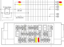
So looking at the Power Source diagram and Driver Side J/B diagram I wonder if I can use one of the empty slots in fuse box (marked in yellow and red on the picture below) to put a fuse and then use one of the connectors on 2C (no 10 or 56) for the red wire powering LEDFOG101. This way the LEDFOG101 module would be powered only when ignition is on (engine running). This would be the least invasive way of powering LEDFOG101.


it sounds like the lights are controlled by the ecu and need an incandescent-type of load, so be prepared to get some load resistors to run in-line with your trigger wires.

It is correct, lights are controlled by ECU but not directly. At least from 2010 electrical diagrams it looks like ECU is controlling relays and there is no current sensing on the "power side" of each relay. Unless of course these are solid state relays, and then I'm screwed.:embarassed:

One thing to keep in mind is that the 10-13 Runners had separate drl's from the fog lights and the folks that did anything mostly just replaced the bulbs or made the fogs independant. That means a lot of folks that probably don't have much interest in this mod. I admire your drive to get it done though!

Yes, I guess people would like to just disable DRL forever. On 10-13 DRL are just front blinkers, so disabling DRL should be as easy as disconnecting wire from contact 5 on the flasher unit (this is DRL input from ECU).

Because I like DRL and Fog base logic (the way they turn on and off) I would like to keep my 4R as close to stock as possible and plug in additional wires to logical places in the existing system. I don't want to plug the unit straight to switches or battery. I want to utilize the ECU logic - I paid big bucks for that ECU so better I use it :wink2:
 

Attachments

  • fusebox.jpg
    fusebox.jpg
    33.8 KB · Views: 3,423
I have electrical diagrams from 2010 (published once on this forum) and I can only assume that there is not much difference between 2010 and 2012. I know the location of flasher is changed but electrical connection seems to be the same.

Yeah, most everything should stay pretty close to that between 2010 and 2013 actually, as I think 2014 had the front fog light change (or was that in 2013?).

So looking at the Power Source diagram and Driver Side J/B diagram I wonder if I can use one of the empty slots in fuse box (marked in yellow and red on the picture below) to put a fuse and then use one of the connectors on 2C (no 10 or 56) for the red wire powering LEDFOG101. This way the LEDFOG101 module would be powered only when ignition is on (engine running). This would be the least invasive way of powering LEDFOG101.

I would say yes, but I dunno where you can find Toyota's fuseholding pins that drop into the box like stock ones, unless you can find one at a junk yard. I don't really care for these newish "micro2" fuses, they're just tiny!

If you didn't mind having a standard ATO blade fuse with a holder sitting under the fuse block's cap, you could just run the wires through one of those slots and connect it under the fuse block, but that's a bit ghetto, and judging by all the work you're putting into this project, no sense in cutting corners now!

It is correct, lights are controlled by ECU but not directly. At least from 2010 electrical diagrams it looks like ECU is controlling relays and there is no current sensing on the "power side" of each relay. Unless of course these are solid state relays, and then I'm screwed.:embarassed:

I think I should have re-phrased that, maybe they're not "controlled" by the ecu, but moreso just "monitored" by the ecu. I think the ecu just checks to make sure there's a load there, but I really can't say for sure since I haven't screwed around with the lighting yet.

Maybe someone can chime in and verify that if one drops an led into the stock housing, does it actually work, or does it:

a) not light up at all
b) throw a code or give an error light somewhere in the dash
c) have other issues

That there would tell you whether or not you can do this. And even if it does throw a code, you can just load it with a resistor like these:

http://www.amazon.com/Resistors-Signal-License-Warning-Cancellor/dp/B004EDF8HY/ref=sr_1_1?ie=UTF8&qid=1446243611&sr=8-1&keywords=trailer+load+resistor

I'm sure it just needs to see a little load on the system if it is checking the status of the lights when they're on, and the only way it can figure that out is by seeing a load. Sorta defeats the purpose of low-load LED lighting though.

Good thread going here! I love to do stuff like this, its what sets your rig apart from the rest! You couldn't imagine the stuff I used to do to my old truck! I'm pretty sure there were at least 12 or 14 relays in that truck, and a lot of them were tied into the alarm for locks and lighting and sirens!

On top of that, I've done two writeups in the past, one for replacing fogs on a 1998~2002 durango using PIAA 510s, and one for bypassing the high beam power cutoff to the relay on the '05 tacomas when they first came out! I think that one's still online at ttora!!!:thumb:
 
I would say yes, but I dunno where you can find Toyota's fuseholding pins that drop into the box like stock ones, unless you can find one at a junk yard. I don't really care for these newish "micro2" fuses, they're just tiny!

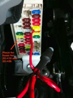
From pictures I saw it looks like everything is in place, just missing fuse (see the picture below). I got 7.5A micro fuse that will fit there so hopefully there will be no surprise when I start hacking into my truck.

Now I have bigger problem. The contact in ECU box I want to tap into will have missing corresponding female in 2C plug. These are some kind of small contacts used in many plugs all over the electrical system in new Toyota cars. Where can I get such contact or at least a piece of wire with this contact, so I can slide it into 2C plug 10 or 56? :gossip:
 

Attachments

  • ECU-Fuse-Box.jpg
    ECU-Fuse-Box.jpg
    102.4 KB · Views: 3,621
Last edited:
I took few minutes to poke under the dash on my 2012 SR5. I can confirm that I need to put fuses in empty slots to activate 2C contact 10 and 56. Now I need to find some piece of wire with mating contact.

4runner-fogdrl-08.jpg


I found flasher just in front of ECU. It is stand alone flasher, not embedded inside ECU. It has plug with all wires accessible. It will be easy task to disconnect DRL wire.

4runner-fogdrl-09.jpg


I also confirmed that Fog Light relay is inside ECU, so either I can plug my FOG connector to one of the connectors near the lamp or go inside the cabin for ECU contact. I am not sure yet.

Now I noticed I have a knee airbag. I guess I will have to disconnect the power from the battery before taking out the lower dash trim, correct?
 
Last edited:
Now I noticed I have a knee airbag. I guess I will have to disconnect the power from the battery before taking out the lower dash trim, correct?

I would highly recommend it. You have to yank on it a little. Better to be safe than sorry.
 
I would highly recommend it. You have to yank on it a little. Better to be safe than sorry.

While having the dash trim out is it safe to plug in the battery?

I need to have the power and start the truck on order to measure the signals on the DRL output from ECU. For stock DRL to come on I need to start the truck, turn on the DRL, release the parking brake and take the shifter out of P. All that with under the dash exposed.
 
While having the dash trim out is it safe to plug in the battery?

I need to have the power and start the truck on order to measure the signals on the DRL output from ECU. For stock DRL to come on I need to start the truck, turn on the DRL, release the parking brake and take the shifter out of P. All that with under the dash exposed.

Yes, you just just want to avoid power during the connect and disconnect.
I knew a stereo installer that didn't disconnect the battery and triggered the airbag while working in that area. Popped him in the head and he died shortly later from a broken neck.
 
Yes, you just just want to avoid power during the connect and disconnect.
I knew a stereo installer that didn't disconnect the battery and triggered the airbag while working in that area. Popped him in the head and he died shortly later from a broken neck.


Got it. Thanks. I will do that. I need my head attached to my neck.
 
I can confirm that I need to put fuses in empty slots to activate 2C contact 10 and 56. Now I need to find some piece of wire with mating contact.

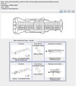
What a bleeping rip-off :yell: I couldn't find any relatively new Toyota on junk yards in the area, so I went to dealer to buy this proprietary contact for ECU plug. There are two types of of connectors in 2C plug:

Toyota Part No.: 82998-24290 TERMINAL, REPAIR W/WIRE
and
Toyota Part No.: 82998-24350 TERMINAL, REPAIR W/WIRE

I suspect one type is going to contacts 1..15 and the other for contacts 15...56 (I don't know which one where). Now the rip-off part: one contact with 15cm ling wire attached costs 15 to 17 bucks at the local dealer. I can get them on-line for 13 bucks a piece but with "standard shipping and handling" I will not save much. It's just a 5 cents contact crimped around with 5 cents wire for crying at loud !!! I'm really pissed. :flame:

Anyway This was the hardest thing (so far) to figure out in the whole project. If all goes as planned I will be able to start installing lights this weekend.

BTW here is the C2 plug (from fsm) I am talking about
 

Attachments

  • C2-connector.JPG
    C2-connector.JPG
    72.4 KB · Views: 2,106
I wonder if anyone can answer that question before I start disassembling the dash tomorrow:

What are the signal levels on DRL Input pin 5 in the Flasher unit (DRL Output from ECU) when DRL is OFF and ON? Does ECU it put +12V when DLR are turned on or ground it? Or maybe it has different some kind of logical signal level?
 
What are the signal levels on DRL Input pin 5 in the Flasher unit (DRL Output from ECU) when DRL is OFF and ON? Does ECU it put +12V when DLR are turned on or ground it? Or maybe it has different some kind of logical signal level?

Here is the answer if anyone wonders. Unfortunately the signal level is the same as most output signals from ECU: Active = connect to ground, not active = Open.
This way ECU turns on all relays where the hot is coming to relay via the fuse and the ECU is grounding the other end to turn it on. And the tame thing is used to turn on DRL in flasher.

So my concept of reusing ECU to turn on and off DRL can't be implemented by simply connecting wire 5 (blue) from OSRAM controller to ECU. It would work opposite way.

I don't know yet which way I will go. I have two options:
1. Connect OSRAM controller the way it was designed meaning DRL input connect with Ignition power (In my case this is the power for the unit) and connect 6 (white) wire with Illumination (or Tail) power. This way Lights would work in Euro mode ignoring original 4Runner DRL switch

2. Create electronic "Signal Reverser" which would convert DRL signal from ECU to have 12V when DRL is ON and Ground (or open) when DRL is OFF. Simply micro relay would work but I am a little concern if ECU would take the load from relay coil. I don;t know what kind of electronic is in ECU and how robust it is. It may not be design to be used with relays (voltage spike on turning off may kill ECU)


I have other update, which kind of sucks. My 4Runner has alarm installed by dealer. What a bloody mess the installer did. Splices and zip-ties all over the place. Made very difficult to access ECU from the front.

Other bad thing I found is 2C plug is behind the ECU (from the front of the car). Almost next to impossible to access this plug. I started looking through the diagrams and I found another empty fuse slot connected to Ignition power. The fuse slot is between TOWING BKUP and KDSS. This fuse is connected to 2D pin 8. 2D is on the front of ECU and would be easy to access if the alarm installer did not made such mess. Anyway I managed to put my 17-bucks wire into plug and I gay Ignition power with my own fuse.

I was looking is if I can find any other empty pin that I could tap into Illumination or tail but when I started to measure the each pin in 2D connector I found that actually my ECU is not 100% the same as ion the FSS diagrams. Connections that should be there do not checked when I measured it with continuity meter. Oh, well. It sucks but what can I do. I will have to improvise.
 

Members online

Forum statistics

Threads
278,315
Messages
3,554,104
Members
248,016
Latest member
Advally Service

Trending content

Back
Top