Positivly or negativly charged?

4wordSOUL

Member
I've got an '04 Sport V8 and I'm wiring a new switch into my dash, it's got two configurations depending on if my Runner is positively or negatively charged. I can't find anything that indicates which and I don't know how to validate on my own. I'm making some guesses from the diagram that came with the switch but frankly I just don't want to **** it up a few times before I get it done right. Anyone know or can advise how I figure it out?
Thx.
 
Register to hide this ad
Use a voltmeter.

Attach the red lead to one wire and the negative lead to the other.

If a positive voltage is displayed, the wire attached to the positive lead is positive.

If a negative voltage is displayed, the wire attached to the positive lead is negative.
 
I've got an '04 Sport V8 and I'm wiring a new switch into my dash, it's got two configurations depending on if my Runner is positively or negatively charged. I can't find anything that indicates which and I don't know how to validate on my own. I'm making some guesses from the diagram that came with the switch but frankly I just don't want to **** it up a few times before I get it done right. Anyone know or can advise how I figure it out?
Thx.

All 4Runners are positively charged and negatively grounded system. If you're adding a new light or whatever, chances are it will be negatively grounded and you'll be "switching" 12vdc (+) positive voltage.
 
You should really own a DMM... its a pretty basic tool for checking a battery or polarity.

They even give them away for free at Harbor Freight if you dont want to buy one.

21.jpg


I highly recommend buying something decent if you like to work on stuff like this often, but even the cheapest option in existence could answer that question for you.
 

Honestly... when it comes to switching, you can switch it however you want... I've hooked up switches switching either the negative end, or the positive end. Its really up to you how to want to run that circuit.

Since there was no mention of a relay... ill go ahead and question your methods... How exactly are you planning on running power to your lights?

Most people who connect lights would probably end up using a relay. So if you are NOT going to use a relay it would be absolutely necessary to measure the amp draw from those lights at the lowest working voltage.

In addition to that, I dont really trust any of those Chinese made import switches to have any current handling capability so I would use a relay no matter what.

Here is an example of the use of a relay...
basic-relay-circuit-diagram-l-e63a66a92447dd69.JPG


Tip: You can get your 12v trigger voltage from anywhere you want, that includes the 12v accessory circuit which turns off when the vehicle is keyed off. Saving you the hassle of having to switch the light manually, or accidentally draining your battery if you forgot to turn them off.

Tip 2: Use fuses... literally, dont cheap out on fusing and calculate fuse sizing based on the wire size and run length, not the intended load. Fuses are there to protect the vehicle wiring.

Tip 3: Ohms law is a heartless b1tch... cross her and you end up with the electrical equivalent of getting ur tires slashed and ur vehicle keyed... Which is basically Post #5

Tip 4: Buy a DMM, learn how to measure voltage, polarity, and amp draw.
 
Last edited:
All of these posts are not detailed guides for your particular situation.

This is the danger of internet DIY advice...steps that an experienced person consider obvious are not covered. This leads to a false sense of knowledge on the part of the DIYer.

It's not what you know that will get you in trouble. It's what you don't know.

I realize this is not rocket science but consider taking a course in basic electricity before moving forward. Hey, even if you do have the required knowledge, the course would just confirm that you are aces!
 

Attachments

  • image.jpg
    image.jpg
    85.2 KB · Views: 1,058
Honestly... when it comes to switching, you can switch it however you want... I've hooked up switches switching either the negative end, or the positive end. Its really up to you how to want to run that circuit...

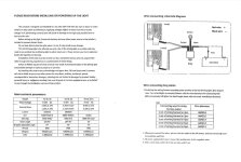
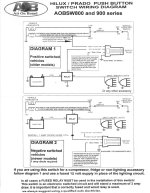
There is a fuse and also a relay built into the wiring harness provided from RUN-D. The wiring schematic from the switch manufacturer is what's confusing. They provided how to wire it for both positive & negative depending on your need. My issue is I have to figure out what I'm working with.

Thanks all you guys for your feedback!
 
Last edited:
It would be really great if you posted up pictures of what you had, relay, harness, switch, instructions that came with it...

We are all legitimately trying to help buy literally flying blind without application specific information.

Following the trend of playing the guessing game... I think you are over thinking this entire thing...

Switches dont give two hoots about what is positive and negative... switches have one job, and that is to either open or close a circuit.

It appears you have a 4 wire switch, and assuming its like others I have used, you only need two wires at a bare minimum to make this circuit work. The other two wires are just to light up the built in LED.

This is the 3rd time I am going to recommend you BUY A DMM. Not owning one and trying to do this job is almost the equivalent of having a box of Phillips head screws, and no Phillips head screw driver when its the only tool you need to complete the job. It can literally answer every question you had in your original post.

...I can't find anything that indicates which and I don't know how to validate on my own....

...Anyone know or can advise how I figure it out?
Thx.

Use said DMM to find continuity between the two wires responsible for switching that circuit on/off. Test continuity by toggling the switch.

Use those two wires to feed the trigger circuit of the relay per the instructions for the relay harness. You will either pull that relay pin to chassis, or more likely supply positive 12v to the relay trigger which I explained above can be obtained from multiple sources... the trucks your oyster, feel free to be creative, or not.

Literally at this point, you are done.

If you really really REALLY REEAALLLYY want the switch to light up, you can feed it with any 12v source you want...

You can connect it to your dash light circuit so it turns on/off with the rest of the dash lights.

You can run it in series with the accessory lights so it turn on only when the light is turned on.

You can run it off your accessory power circuit so its only on when the car is on.

Or you can just cut them off and call it a day... or throw a little electrical tape on the ends and keep it tidy and secure for another day.

I really hope this helps.
 
Last edited:
I bet there are other 4NR owners in his town/city that he can tap into for help. We're making this simple project sound like a monumental exercise in electrical engineering and it really shouldn't be that way!

But, it'd be nice to have someone show the OP how to do these types of projects so that he can gain confidence and do similar projects on his own.
 
It would be really great if you posted up pictures of what you had, relay, harness, switch, instructions that came with it...

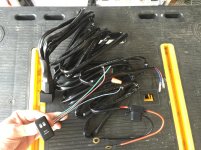
Here you go. I am going to buy whatever tools/testing device necessary for me to do this on my own.

I agree this is simple I just want to do it right the first time.

I want the switch to light up when the parking lights are on as it should, I don't want the lights to turn off when the high beams are on.

The harness appears to be decent quality (the black switch wire end was barley connected but I'll fix that), it has a 30amp fuse built in.
 

Attachments

  • IMG_8923.jpg
    IMG_8923.jpg
    137.2 KB · Views: 1,012
  • RUN-D LED light diagram.jpg
    RUN-D LED light diagram.jpg
    130.7 KB · Views: 1,005
  • switch diagram-1.jpg
    switch diagram-1.jpg
    131.8 KB · Views: 1,097
Last edited:
Thanks... much better, should have started with that OP... the instructions are pretty clear, not sure what the problem is.

If you want to hook it up to your parking lights, then do that, just find the circuit, measure that wire with a DMM to see if its + or -, then connect per the instructions.

Personally I would ignore the recommendation from the instructions completely...

You have a separate switch... you can control it completely independent of your high beams or anything else.

Make short work of this and buy a pack of these.
https://www.amazon.com/gp/product/B00SUTYYS2/ref=oh_aui_search_detailpage?ie=UTF8&psc=1

Tap the accessory 12v circuit from the fuse panel inside the cab, and connect it to the green wire of the switch. Done. That wire is hot 12v+ so it would follow the positively switched diagram.
 
...Make short work of this and buy a pack of these.
https://www.amazon.com/gp/product/B00SUTYYS2/ref=oh_aui_search_detailpage?ie=UTF8&psc=1

Tap the accessory 12v circuit from the fuse panel inside the cab, and connect it to the green wire of the switch. Done. That wire is hot 12v+ so it would follow the positively switched diagram.

Thanks, I thought I'd seen that somewhere in a video or some page but I'd forgotten about it (just got out of the hospital from surgery and I'm still recovering). I've got my list of tools I need to get and with all your feedback I feel confident I can get it installed properly.

Thanks for all the feedback folks!
 
...get a DMM and fuse TAP...

I got a DMM and the fuse TAPs will be here today. After searching YouTube I can't find a decent video or explanation on how to run the wires into the cab to connect to the switch. From what I found on T4R it looks like I can:
  1. cut the switch contacts off the wires connecting the switch to the relay
  2. cut off the little nipple on the large firewall grommet and feed the wires through the firewall to the cab
  3. reconnect the switch contacts to the LED wires and connect the LED wires to the switch in the dash
I get the impression this is the cleanest way to wire anything from the engine bay to a switch in the cab, yes? Am I missing anything?

I am likely to add a number of lights in the future: roof light bar, bumper mounted driving lights, side and rear lights. If I knew exactly what I needed to run I'd run all the wires now since I'll be in there but I don't. Is there anything I can do or should do to prepare for this eventuality since I'll be going through from the engine bay to the cab anyway?
 
Last edited:
I got a DMM and the fuse TAPs will be here today. After searching YouTube I can't find a decent video or explanation on how to run the wires into the cab to connect to the switch. From what I found on T4R it looks like I can:
  1. cut the switch contacts off the wires connecting the switch to the relay
  2. cut off the little nipple on the large firewall grommet and feed the wires through the firewall to the cab
  3. reconnect the switch contacts to the LED wires and connect the LED wires to the switch in the dash
I get the impression this is the cleanest way to wire anything from the engine bay to a switch in the cab, yes? Am I missing anything?

I am likely to add a number of lights in the future: roof light bar, bumper mounted driving lights, side and rear lights. If I knew exactly what I needed to run I'd run all the wires now since I'll be in there but I don't. Is there anything I can do or should do to prepare for this eventuality since I'll be going through from the engine bay to the cab anyway?

The two most common, and probably easiest access points into the cab from the engine bay are the two large grommets on both the passenger and driver side on the firewall.

Word of caution... be stupid careful when doing so. Be absolutely sure not to compromise the factory wiring so dont start jabbing sharp objects though it or try to run it too close to the factory bundles. Don't use a screw driver or ice pick... Get it started using a pull wire with a rounded head and tape the wires you want to pull to it. Its not fancy, but I use some scrap solid copper wire from a home remodel.

Tip: Depending on what you are feeding though, the size, type of insulation on the wire, or jacket material, you might feel a bunch of resistance... Just like anything else you might try to penetrate, you might need lube. Non conductive dielectric grease would be a good choice.
https://www.amazon.com/Permatex-22058-Dielectric-Tune-Up-Grease/dp/B000AL8VD2

Regarding future proofing, its completely up to you what you want to run... but at least you are thinking ahead now... but ill give you some examples as to how I did it. You can decide how "crazy OCD" you want to get.

I spent a good amount of time planning, I only want to do it once and do it right, and I dont like fussing with critical areas like that constantly adding and removing wires.

I basically planned out switches, blank future adds, medium power, and a 50a mains run for a DC sub-panel inside the car....

I made my own "concentric wire harness" and sized wires accordingly. https://www.youtube.com/watch?v=GLjKQHMU57k
I used 18 awg for control and indicators wire (switches and LED)
I used 14 awg for medium power
I used 10 awg for my 50 amp mains run for my dc-sub panel

Realistically you can use anything from 16 to 24 awg for control, but 18-20 is a good place to be. I went with 18 for more mechanical reliability, and because its easier to crimp.

Then do a concentric wrap to turn it into one big wire harness... Not my work, but should look something like this.

concentric_layers.jpg~original


HandlayvsNone_zpscbd308fa.jpg~original


If that's literally too much work, then find some "multi conductor cable" in 18 to 20 awg... STRANDED... dont use solid core cat5 or something like that.

40637.jpg
flexible-multicore-cables-250x250.jpg~original


The latter being perfectly acceptable and the easy choice, the difference being the other is completely custom and built to your own spec / needs.

If you want to have a clean finish... crimp your end connections where needed, and use some type of quick disconnect connector to make it serviceable... just like how the factory did it.

You can either crimp your own connectors like these:
13.jpg~original


Or buy something like this and make only straight butt connections... not as clean, but works just as well. Sometimes it adds bulk, which is why the first option is preferred and looks a bit more professional.

Many electronic shops sell something like this with the male and female end with maybe about 6-10 inches of wire total. Ready to cut and crimp.

pl3630485-custom_8_pin_automotive_wiring_harness_car_stereo_radio_wiring_harness.jpg~original


I know this is a lot to take in... probably way more than you need, but its just an example so you can get some ideas for your own project.

 
Last edited:
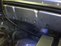
Thank you Bumbo and everyone for your helpful comments. I'm going to finish it tonight and I have one more question. The spot I'd like to ground the relay at, what size would the bolts be?
 

Attachments

  • IMG_8927.jpg
    IMG_8927.jpg
    129.4 KB · Views: 170
Thank you Bumbo and everyone for your helpful comments. I'm going to finish it tonight and I have one more question. The spot I'd like to ground the relay at, what size would the bolts be?

Well, it's a Toyota, so it's going to be metric. Hard to tell from that photo, but probably M5, maybe M6. Either find a bolt that fits and measure it, or thread some taps in there by hand until you find one that fits.
 

Members online

Forum statistics

Threads
278,312
Messages
3,554,083
Members
248,016
Latest member
Advally Service

Trending content

Back
Top