Rear lower control arm bracket dimensions

Kwikvette

New member
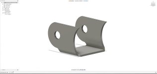
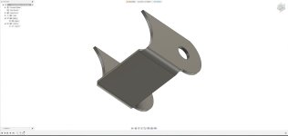
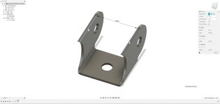
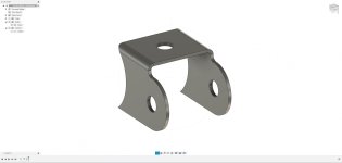
Does anyone have the dimensions drawn out for the welded on brackets (on the axle housing) for the rear lower control arms?

Another person's picture (with a single measurement shown) has gotten me this far -

2 3/4" length from the edge of the radius cut to the axle housing tube; add 5/8" in length where it wraps around the tube due to the 3" radius on the housing

9/16" hole (assuming 14mm bolt) for the bolt that holds the control arm

15/16" from the side edge to the center of said hole

2" radius cut at the mount end (opposite of the axle housing)

1" from the edge of the radius cut to the center of the bolt hole

How far am I off? Again this is from an internet picture as I got rid of my 4Runner a few years ago
 
Register to hide this ad
No I just don't have the measurements as I replace the rear axle housings when they rust up. :)

You only gain 2 to 3 years max in the rust belt if you weld the brackets on or replace them.

As I had to replace 3 so far on 3 different 3rd gens. Then super clean the steel to seal off the oxygen so they last longer.

I am actually thinking of having this 3rd one power coated when I have all apart.. :)


Sent from my SM-A536V using Tapatalk
 
No I just don't have the measurements as I replace the rear axle housings when they rust up. :)

You only gain 2 to 3 years max in the rust belt if you weld the brackets on or replace them.

As I had to replace 3 so far on 3 different 3rd gens. Then super clean the steel to seal off the oxygen so they last longer.

I am actually thinking of having this 3rd one power coated when I have all apart.. :)


Sent from my SM-A536V using Tapatalk

Wouldn't be for me; I'm in CA and hell...even my 80 series LC had an immaculate frame. My '03 GX470's frame looks like it's from 2023.

Someone posted on the other 4R forum needing to replace his so I asked for dimensions and never got them.

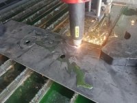
Thought I'd do the favor of making a DXF available for anyone and if needed, cut out the part for him to replace with.
 
Wouldn't be for me; I'm in CA and hell...even my 80 series LC had an immaculate frame. My '03 GX470's frame looks like it's from 2023.


Someone posted on the other 4R forum needing to replace his so I asked for dimensions and never got them.


Thought I'd do the favor of making a DXF available for anyone and if needed, cut out the part for him to replace with.
Be grateful. :) 50% of the owners live in the rust belt....

Sent from my SM-A536V using Tapatalk
 
Well, we'll see how they come out as his measurements weren't the best
 

Attachments

  • Screenshot 2023-08-18 101243.jpg
    Screenshot 2023-08-18 101243.jpg
    99.9 KB · Views: 975
  • Screenshot 2023-08-18 101228.jpg
    Screenshot 2023-08-18 101228.jpg
    97.9 KB · Views: 964
Good deal as we have to start getting simpleies for parts. I hope they work out great for you. :)

Sent from my SM-A536V using Tapatalk
 
Grateful? No way!


I lived in the east coast and midwest; no reason to stay!


I chose to live on the west coast :biggrin1:
Just like I choose to stay here. I like seasons and have plenty of water.

I can deal with the rust as it's just how it is here. It's actually minor considering other factors..


Great Job on those brackets. They will work. :)

Sent from my SM-A536V using Tapatalk
 
Good deal as we have to start getting simpleies for parts. I hope they work out great for you. :)

Sent from my SM-A536V using Tapatalk

Well not for me again!

I'm just drawing them up, then I'll cut them out and ship them to him.

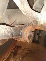
Here's a pic of his own 4R
 

Attachments

  • IMG_20230818_163955085.jpg
    IMG_20230818_163955085.jpg
    128.9 KB · Views: 1,057
Getting thin.. I would remove the control arm. Weld up the outside of the bracket with a thick washer and some metal ground it smooth and good for another 5 years. I have had the uppers rust off. The lowers on thr frame just loose and the upper on the pipe rust off.

All fixable.. lol. Rust belt hard on things.

You may have some business if you can replicate all the body mounts and frame brackets that are disappearing from Toyota inventory. :)

Sent from my SM-A536V using Tapatalk
 
Getting thin.. I would remove the control arm. Weld up the outside of the bracket with a thick washer and some metal ground it smooth and good for another 5 years. I have had the uppers rust off. The lowers on thr frame just loose and the upper on the pipe rust off.

All fixable.. lol. Rust belt hard on things.

You may have some business if you can replicate all the body mounts and frame brackets that are disappearing from Toyota inventory. :)

Sent from my SM-A536V using Tapatalk

Fabricator here; he's in West Virginia otherwise I'd gladly cut off and weld the new ones. We're making it a pair now.

Even though the bracket is 1/8" like the frame, I'll be cutting it out of 10 gauge.

Long as it's rust proofed afterward it should hold up fine.

Got his final dimensions and I'll be cutting up parts tomorrow. Will post here once I do so.
 

Attachments

  • Screenshot 2023-08-19 111227.jpg
    Screenshot 2023-08-19 111227.jpg
    113.5 KB · Views: 999
  • Screenshot 2023-08-19 111243.jpg
    Screenshot 2023-08-19 111243.jpg
    95.7 KB · Views: 993
Fabricator here; he's in West Virginia otherwise I'd gladly cut off and weld the new ones. We're making it a pair now.

Even though the bracket is 1/8" like the frame, I'll be cutting it out of 10 gauge.

Long as it's rust proofed afterward it should hold up fine.

Got his final dimensions and I'll be cutting up parts tomorrow. Will post here once I do so.

they have like a 5 deg angle heading outward off the rear axle assembly. I did these a while back they are kind of biach to get right.
 
Last edited:
they have like a 5 deg angle heading outward off the rear axle assembly. I did these a while back they are kind of biach to get right.

I hope he can get it right then; he says he welds so angle and all would be on him.

I love my Klein digital angle finders.
 
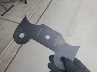
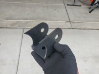
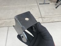
So, I went ahead and cut up a test piece out of some scrap 1/8"

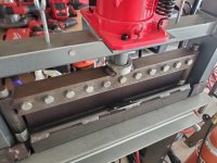
Only issue I ran across, which I planned ahead for was, performing the second bend on my brake

For that reason I added relief cuts to both sides and finished the second bend on my vise

End result ended up being 2.375" wide inside the wings
 

Attachments

  • 20230819_154203.jpg
    20230819_154203.jpg
    134.2 KB · Views: 978
  • 20230819_154345.jpg
    20230819_154345.jpg
    101.4 KB · Views: 957
  • 20230819_154936.jpg
    20230819_154936.jpg
    129 KB · Views: 940
  • 20230819_155438.jpg
    20230819_155438.jpg
    119.3 KB · Views: 943
  • 20230819_155515.jpg
    20230819_155515.jpg
    122.2 KB · Views: 966
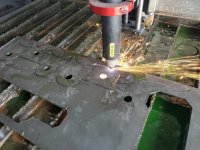
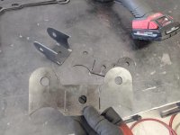
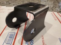
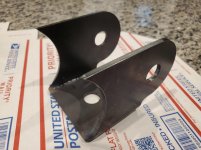
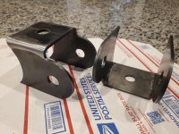
Pushed each relief cut out .0775" not to mention lengthening it by .125" and cut the real set out of 10 gauge

Afterward I bent and welded them up and now they're ready to go
 

Attachments

  • 20230819_162226.jpg
    20230819_162226.jpg
    133.6 KB · Views: 938
  • 20230819_162727.jpg
    20230819_162727.jpg
    130.3 KB · Views: 957
  • 20230819_172119.jpg
    20230819_172119.jpg
    113.4 KB · Views: 1,079
  • 20230819_172153.jpg
    20230819_172153.jpg
    119.5 KB · Views: 947
  • 20230819_172058.jpg
    20230819_172058.jpg
    127.9 KB · Views: 966
So, I went ahead and cut up a test piece out of some scrap 1/8"

Only issue I ran across, which I planned ahead for was, performing the second bend on my brake

For that reason I added relief cuts to both sides and finished the second bend on my vise

End result ended up being 2.375" wide inside the wings

That's bad ass. i envy skills like yours.
 

Members online

No members online now.

Forum statistics

Threads
278,306
Messages
3,554,044
Members
248,016
Latest member
Advally Service

Trending content

Back
Top