
Ref: DIY: Replace Servo Sub-Assy
------------------------------
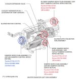
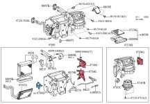
Parts locations
04300 Parts Location (pdf)
Part Numbers:
Toyota 87106-35150 (All models) | Denso 063700-8860
Toyota 87106-35120 (All models) | Denso 063700-8860
Toyota 87106-35180 (All models) | Denso 063800-0660
Toyota 87106-35170 (Limited Only) | Denso 063800-0660
120 and 180 seem to go bad the most and cause all the loud clicking and buzzing sounds.
These two actuators are reachable without taking apart the dash, but the back screws on each one are a pain in the ass to reach. The back screw of the lower actuator requires drilling a hole through the side of the blower housing unit.
------------------------------
Part 120
If you want to save a little money, buy Denso 063700-8860, instead of the much more expensive Toyota 87106-35120. The mounting bracket and white plastic alignment plate are removable and can be swapped onto the new motor.
Part 180
The rotating lever arm on this motor is not removable and appears to be a press fitting. To replace this actuator, you need to buy the entire unit, Toyota 87106-35180.
Part 150
If you have to replace this actuator behind the right side of the glove box, most likely you will need to follow the repair manual and take apart the entire dash. May the auto gods be with you on this perilous journey.
Part 170
Limited only. This is easily reachable without taking apart the dash.
------------------------------
Note: The motors have plastic gears inside, and they wear down over time. Imho, it's worth replacing both servos (120 and 180) at the same time. If you have to replace 150, you might as well replace the others as well, since you will have to take apart the entire dash to gain access to 150, behind the glove box.
------------------------------
TOOLS
OPTIONAL TOOLS
------------------------------
REMOVING ACTUATORS / SERVOS
Upper actuator (120)
Disconnect the wiring plug.
Remove the lower back screw, with a long screw Phillips screwdriver. You have to angle the screw driver and apply pressure to keep it locked in on the screw. Then remove the other two screws. Remove unit carefully.
After you remove it, take a marker and draw lines on the old unit to mark the position of the (white plastic) alignment plate, or take photos.
Lower actuator (180)
Disconnect the wiring plug.
Remove the upper back screw. To reach the upper back screw, drill a 3/8" or 1/2" hole into the left side of the blower housing unit. Hole location is approximately 4" set back from front edge of unit. To do this, you'll need a very small handheld drill, right-angle drill, or drill with right-angle attachment. Then slip a long Phillips screwdriver through the hole to reach the back screw. This is the most difficult screw.
After you remove it, take a marker and draw lines on the old unit to mark the position of the (white plastic) rotating arm, or take photos.
------------------------------
INSTALLING ACTUATORS / SERVOS
Grease Mechanisms
Optional. You might have noticed some grease left over on the mechanisms from the factory. If you have very little or no grease, or it's a grimy mess, it might be a good time to wipe things down and reapply lubrication.
Don't grease anything on the new actuators. Only grease the grooves/track, pins, and rotation points for the levers on the main ac unit. Don't go crazy with the grease and make a mess.
Upper Actuator (120)
Install upper actuator first. Before installing, do a test fit. Make sure the grooves on the alignment plate line up with the pins on the plastic pieces attached to the housing unit. Recall the marks you placed on the old actuator. If your new actuator plate is not in similar alignment, plug in the wire for the actuator, turn the key on and adjust the AC temp.
I found it easier to remove the alignment plate from the motor, and align the plate onto the three pins. Then put the motor on and snap it into the center hole plate. While holding it against the wall, install the front screw first. Then install the upper and lower back screws.
Optional: Some people choose to replace the screws with #8 hex screws, 1/2" long. For this, you'll need a socket set.
Lower actuator (180)
Before installing, do a test fit. Make sure the pins on the rotating arm line up with the grooves on the housing unit gears. Recall the marks you placed on the old actuator. If your new actuator arm is not in similar alignment, plug in the wire for the new actuator, turn the key on and adjust the AC temp.
Once you have the actuator arm rotated to the correct position, install the lower actuator. Use the hole on front end of the the mounting bracket and place onto the plastic alignment pin on the housing unit.
Next, ensure the two metal pins on the plastic rotating arm are seated into the appropriate gears/levers. Once they are seated, hold it in place and screw in the front screw first. Next install the bottom screw.
For the back screw, replace the screw with #8 (1/2") sheet metal screw. Feed a 6" long 1/4" drive extension through the hole you drilled earlier, and carefully attach a 7mm socket and screw. Carefully line up the screw and tighten. Double check front two screws to ensure everything is secure.
Place a piece of duct or electrical tape on the inside and outside of the blower unit to cover the freshly drilled hole.
------------------------------

------------------------------
Parts locations
04300 Parts Location (pdf)
Part Numbers:
Toyota 87106-35150 (All models) | Denso 063700-8860
Toyota 87106-35120 (All models) | Denso 063700-8860
Toyota 87106-35180 (All models) | Denso 063800-0660
Toyota 87106-35170 (Limited Only) | Denso 063800-0660
120 and 180 seem to go bad the most and cause all the loud clicking and buzzing sounds.
These two actuators are reachable without taking apart the dash, but the back screws on each one are a pain in the ass to reach. The back screw of the lower actuator requires drilling a hole through the side of the blower housing unit.
------------------------------
Part 120
If you want to save a little money, buy Denso 063700-8860, instead of the much more expensive Toyota 87106-35120. The mounting bracket and white plastic alignment plate are removable and can be swapped onto the new motor.
Part 180
The rotating lever arm on this motor is not removable and appears to be a press fitting. To replace this actuator, you need to buy the entire unit, Toyota 87106-35180.
Part 150
If you have to replace this actuator behind the right side of the glove box, most likely you will need to follow the repair manual and take apart the entire dash. May the auto gods be with you on this perilous journey.
Part 170
Limited only. This is easily reachable without taking apart the dash.
------------------------------
Note: The motors have plastic gears inside, and they wear down over time. Imho, it's worth replacing both servos (120 and 180) at the same time. If you have to replace 150, you might as well replace the others as well, since you will have to take apart the entire dash to gain access to 150, behind the glove box.
------------------------------
TOOLS
- Long Phillips screwdriver
- Duct Tape
- Drill
- 3/8" or 1/2" drill bit
- Right angle drill attachment
- Marker
- Towel
- Good lighting
OPTIONAL TOOLS
- Silicone paste
- Ratchet with 1/4" drive
- 6" long drive extension for 1/4" drive
- 7mm socket for 1/4" drive
- #8 (1/2") sheet metal hex head screws (6)
- Electrical tape
------------------------------
REMOVING ACTUATORS / SERVOS
- Remove glove box (no screws)
- Remove air filter (no screws)
- Remove hidden glove box (1 screw)
- Remove lower interior liner (1 screw)
- Disconnect wiring for control boxes (2 plugs)
- Disconnect wiring for blower (1 plug)
- Remove blower (3 screws)
- Remove air duct (no screws, 1 tab in back)
- Disconnect wiring for actuators (120 and 150)
- Remove screws for upper actuator and remove (120)
- Remove screws for lower actuator and remove (180)
Upper actuator (120)
Disconnect the wiring plug.
Remove the lower back screw, with a long screw Phillips screwdriver. You have to angle the screw driver and apply pressure to keep it locked in on the screw. Then remove the other two screws. Remove unit carefully.
After you remove it, take a marker and draw lines on the old unit to mark the position of the (white plastic) alignment plate, or take photos.
Lower actuator (180)
Disconnect the wiring plug.
Remove the upper back screw. To reach the upper back screw, drill a 3/8" or 1/2" hole into the left side of the blower housing unit. Hole location is approximately 4" set back from front edge of unit. To do this, you'll need a very small handheld drill, right-angle drill, or drill with right-angle attachment. Then slip a long Phillips screwdriver through the hole to reach the back screw. This is the most difficult screw.
After you remove it, take a marker and draw lines on the old unit to mark the position of the (white plastic) rotating arm, or take photos.
------------------------------
INSTALLING ACTUATORS / SERVOS
Grease Mechanisms
Optional. You might have noticed some grease left over on the mechanisms from the factory. If you have very little or no grease, or it's a grimy mess, it might be a good time to wipe things down and reapply lubrication.
Don't grease anything on the new actuators. Only grease the grooves/track, pins, and rotation points for the levers on the main ac unit. Don't go crazy with the grease and make a mess.
Upper Actuator (120)
Install upper actuator first. Before installing, do a test fit. Make sure the grooves on the alignment plate line up with the pins on the plastic pieces attached to the housing unit. Recall the marks you placed on the old actuator. If your new actuator plate is not in similar alignment, plug in the wire for the actuator, turn the key on and adjust the AC temp.
I found it easier to remove the alignment plate from the motor, and align the plate onto the three pins. Then put the motor on and snap it into the center hole plate. While holding it against the wall, install the front screw first. Then install the upper and lower back screws.
Optional: Some people choose to replace the screws with #8 hex screws, 1/2" long. For this, you'll need a socket set.
Lower actuator (180)
Before installing, do a test fit. Make sure the pins on the rotating arm line up with the grooves on the housing unit gears. Recall the marks you placed on the old actuator. If your new actuator arm is not in similar alignment, plug in the wire for the new actuator, turn the key on and adjust the AC temp.
Once you have the actuator arm rotated to the correct position, install the lower actuator. Use the hole on front end of the the mounting bracket and place onto the plastic alignment pin on the housing unit.
Next, ensure the two metal pins on the plastic rotating arm are seated into the appropriate gears/levers. Once they are seated, hold it in place and screw in the front screw first. Next install the bottom screw.
For the back screw, replace the screw with #8 (1/2") sheet metal screw. Feed a 6" long 1/4" drive extension through the hole you drilled earlier, and carefully attach a 7mm socket and screw. Carefully line up the screw and tighten. Double check front two screws to ensure everything is secure.
Place a piece of duct or electrical tape on the inside and outside of the blower unit to cover the freshly drilled hole.
------------------------------
Attachments
Last edited:


