barryhiram
New member
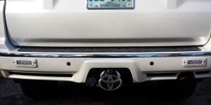
First, I take no credit for thinking of this mod. Back in 2012 [MENTION=68685]Ducmonsta[/MENTION] posted an excellent write-up installing SRM2’s in rear factory bumper. Immediately this was added to my “to do” list, so here’s credit where credits due!
Second, many thanks go out to [MENTION=120150]TotalAutomotiveLV[/MENTION] for providing outstanding customer service, fast shipping, and best price! Sent PM Monday, order shipped Tuesday, package arrived Thursday, thanks Chas and Mike!
Ok, now for the meat and potato’s………………..
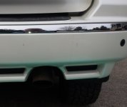
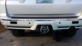
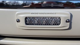
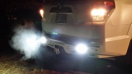
Objective: Increase rear night time visibility when backing up (not many street lights in New Hampshire), hooking up trailer, loading trailer, and tying down 4 wheelers. Paint mounting flange to match factory paint. As with all my mods, maintain an OEM look.
Difficulty: 5-6, basic wiring. It’s not difficult, but some may be reluctant to cut their perfectly good bumper. “Cut it once, cut it big” doesn’t apply here, accuracy is key.
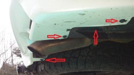
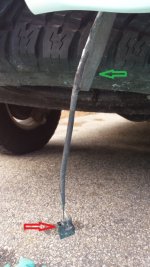
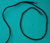
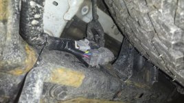
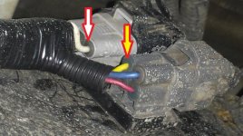
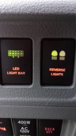
Wiring: Since lights draw only 3.3 amps (3,136 LM output), I will not be installing included relay kit. Will direct wire to trailer plug harness located driver side rear frame rail. Yellow wire is positive (+) when vehicle is shifted to reverse, White wire is ground (-). Lights will turn on whenever vehicle is in reverse or when I turn on already install AOB aux switch http://www.toyota-4runner.org/5th-gen-t4rs/159174-factory-style-fog-light-switch-fits-knock-out.html
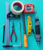
Tools required: Tape measure, Masking Tape, Air Saw, Square, Grease Pencil, Razor knife, Ratchet, extension, 10mm socket, File, Cordless drill , ¼” & 3/8” drill bits, Wire crimper/stripper, Wire Ties, Soldering iron/solder, Heat shrink, Electrical Tape (3M Super 88), 7/16” wrench, 7/64”, 5/32” Allen wrenches, paint, primer, red scuff pad.
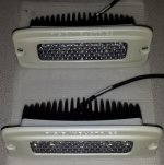
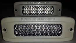
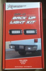
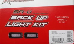
Rigid Industries SR-Q Back Up Light Kit, part #98003. Include harness, relay, switch, mounting hardware, wiring diagram, and template.
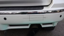
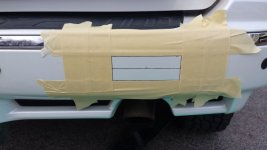
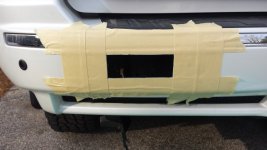
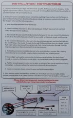
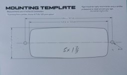
I found the included template too large so I did not use, instead measured housing and found mounting hole should be 1 7/8” x 5”
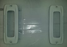
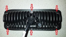
Time to disassemble housing to prep for paint, using 7/64” allen wrench, remove 6 bolts. Note: two center bolts are slightly longer than the four outside bolts. While holding back of housing and a finger on lens, carefully remove mounting flange.
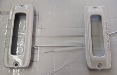
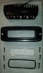
Light housing disassembled. There are two gaskets to prevent moisture intrusion, one seals mounting flange to housing, one between clear lens/ and mounting flange. Also, reflector assembly is not attached to housing, so be careful when disassembling.
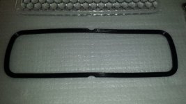
Lens to flange gasket has a flat ribbed side and a curved side. The flat ribbed side goes toward clear lens, curved side goes toward flange. If you install backwards, light won’t seal properly…………..remember this!!!!!!!
Second, many thanks go out to [MENTION=120150]TotalAutomotiveLV[/MENTION] for providing outstanding customer service, fast shipping, and best price! Sent PM Monday, order shipped Tuesday, package arrived Thursday, thanks Chas and Mike!
Ok, now for the meat and potato’s………………..
Objective: Increase rear night time visibility when backing up (not many street lights in New Hampshire), hooking up trailer, loading trailer, and tying down 4 wheelers. Paint mounting flange to match factory paint. As with all my mods, maintain an OEM look.
Difficulty: 5-6, basic wiring. It’s not difficult, but some may be reluctant to cut their perfectly good bumper. “Cut it once, cut it big” doesn’t apply here, accuracy is key.
Wiring: Since lights draw only 3.3 amps (3,136 LM output), I will not be installing included relay kit. Will direct wire to trailer plug harness located driver side rear frame rail. Yellow wire is positive (+) when vehicle is shifted to reverse, White wire is ground (-). Lights will turn on whenever vehicle is in reverse or when I turn on already install AOB aux switch http://www.toyota-4runner.org/5th-gen-t4rs/159174-factory-style-fog-light-switch-fits-knock-out.html
Tools required: Tape measure, Masking Tape, Air Saw, Square, Grease Pencil, Razor knife, Ratchet, extension, 10mm socket, File, Cordless drill , ¼” & 3/8” drill bits, Wire crimper/stripper, Wire Ties, Soldering iron/solder, Heat shrink, Electrical Tape (3M Super 88), 7/16” wrench, 7/64”, 5/32” Allen wrenches, paint, primer, red scuff pad.
Rigid Industries SR-Q Back Up Light Kit, part #98003. Include harness, relay, switch, mounting hardware, wiring diagram, and template.
I found the included template too large so I did not use, instead measured housing and found mounting hole should be 1 7/8” x 5”
Time to disassemble housing to prep for paint, using 7/64” allen wrench, remove 6 bolts. Note: two center bolts are slightly longer than the four outside bolts. While holding back of housing and a finger on lens, carefully remove mounting flange.
Light housing disassembled. There are two gaskets to prevent moisture intrusion, one seals mounting flange to housing, one between clear lens/ and mounting flange. Also, reflector assembly is not attached to housing, so be careful when disassembling.
Lens to flange gasket has a flat ribbed side and a curved side. The flat ribbed side goes toward clear lens, curved side goes toward flange. If you install backwards, light won’t seal properly…………..remember this!!!!!!!
Attachments
-
 Back of light.jpg106.8 KB · Views: 5,122
 -
 Back of light2.jpg74.7 KB · Views: 5,105
 -
 Gasket.jpg48.9 KB · Views: 5,057
 -
 Layout2.jpg57.3 KB · Views: 5,222
 -
 Rigid SR-Q(2).jpg62 KB · Views: 5,202
 -
 Rigid SR-Q.jpg61.7 KB · Views: 5,446
 -
 Tools.jpg83.5 KB · Views: 5,488
 -
 Wire Diagram.jpg85.8 KB · Views: 5,624
Last edited: