Dewyz1100
New member
Hi there 4Runner Forum folks... I guess you could call this my first "Repair Thread"...
My 1998 4Runner SR5 has just over 160K miles, and to my knowledge I am the third owner. The truck has spent most of its life in the rust belt of the northeast where pavement is not black in the winter, but white with all of the road salt and calcium that the DOT dumps on them. Needless to say, this thread is for those of us that call this area home - and to show folks in the other areas of the country how lucky they have it...
To start off with, my 4Runner required rear axle seals - and props to BigFishAllDay for an excellent build thread sticky showing the details of this operation. I used this sticky as a jumping off point for what was to come next - the swap of the rear axle housing.
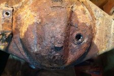
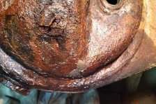
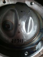
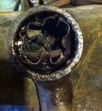
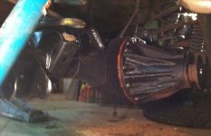
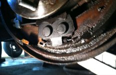
Please note - This is one expensive task that is forced upon some of us in the rust belt simply due to the fact that the rear differential "pumpkin" cover is not a bolt on item. Toyota in their infinite wisdom decided not only to not make this piece an integrated part of the axle housing, but to simply spot weld two brackets onto it as well - opening the door to two "salt shelves" that will corrode and eventually vibrate causing a hole for the gear oil to leak out of. The following information and the dollar signs will highlight more than anything why Toyota will likely NEVER issue a recall for these issues...
Just the parts:
A new rear axle housing from Toyota was over $1K...
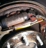
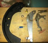
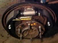
Car Quest rear brake shoes, cylinders, and hardware kit was over $200...
Toyota axle bearings, seals, ABS rotors, retainers, spacers was over $400...
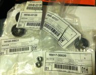
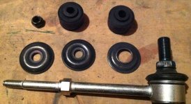
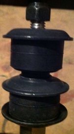
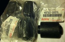
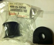
Stabilizer links and bushings for it and the lower control arms were over $200...
Plan on at least $100 in new hardware, and another $100 in consumables for cleaner, gear oil, penetrating oil...and all this is just to start with...more on that later...
First step - Locate the sticky for replacing rear axle seals on this site. Follow those directions for tear down, and buy the parts listed within that thread for reassembly later...
I will add to that sticky by saying that the ABS sensors are a PITA to remove, and at over $200each, one should take great care to not damage them. Unfortunately for us rust belt folks, it is not as simple as a flat blade screwdriver and a bit of prying... Remove the bolt, remove the three closest ABS wire clamps/mounts, hose down the sensor base with penetrating oil, and place a set of channel locks firmly at the base of the sensor. Begin to twist back and forth - rotating the sensor 1/4" in each direction to get it moving. Add additional oil every few rotations to aide the movement. Once you are able to rotate the sensor back and forth without a death grip on the channel locks, rotate so that the tab is above the pad it mounts to.
Use a small pry bar under the tab using the top of the axle housing for leverage to apply a little pressure while continuing to use the channel locks to wiggle the sensor back and forth. Feel free to use additional oil to aide in this process, but this was the only way I could remove my ABS sensors from my housing.
On to where the rear axle sticky ends...
**Plan on replacing almost all hardware, and just about everything else depending on the level of corrosion that your truck has, and how deep your pockets are***
-Begin draining the gear oil from the rear axle housing. Both the drain plug and the fill plug use the same socket size of 24mm. I was lucky and these came out with a little propane from the Bernzo...
-Disconnect the drive shaft from the 3rd member. I replaced all the U-joints and the drive shaft hardware a year ago, so I am unsure of the original bolt specs. The specs for the replacement hardware I used are:
4 Bolts: Stainless Steel M10 (1.00)pitch x 3cm
4 Split Washers: Stainless M10
4 Flat Washers: Stainless M10
4 Lock Nuts: Stainless M10 (1.00)pitch
If memory serves, both the original hardware, and the new hardware both are 14mm. However, it is a tight fit using a socket on the forward side, and only an open ended wrench will fit behind the flange of the 3rd member. NOTE - the bolts can't be much longer than 3cm as the flange for the 3rd member prevents anything much more than the lock nut to fit in there.
-Remove the 3rd member from the axle housing. There are 10 nuts that use threaded studs to secure the 3rd member to the axle housing. You will need a 12mm socket and some heat to remove these. Again, I got lucky and only sheared off two studs in this process - the others came out fairly easy, but most of the time the studs came out along with the nuts. I intend to simply use quality bolts instead of studs for the re-installation.
For whatever reason, my 3rd member was seized onto one of the studs that sheared off flush with it. This one was located in the upper right if you are looking at it from the drive shaft side. It took about an hour of penetrating oil, heating, hammering, and prying to finally free it from the housing.
Once it was out, I chipped off all loose surface rust, then bathed it in a good amount of brake cleaner both inside and out. I also took the opportunity to put a couple thick coats of primer on it before a couple coats of rubberized undercoating. Just be sure to tape off every part of the exposed gears, and keep the holes for the studs clear of what you are spraying...
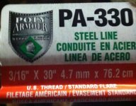
-Remove all E-Brake, and brake line bolts. These can all be removed with a 12mm socket, and a bit of heat... I saved the clamps for the brake lines, and luckily the rubber brake hose to the axle T was in good shape, and the metal lines came out with a little oil - but I was planning to replace the metal lines so I was not concerned with them breaking.
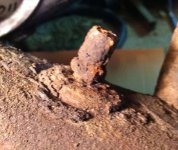
The only bolt that did not come free was the one holding the E-Brake Guide to the bracket in the center of the differential cover... Go figure... I knew if it was rusty enough to cause the cover to leak gear oil, it was likely fall to pieces in the attempt to remove the bolt that was secured to it.
At this point everything but the suspension components should be removed and/or free from the axle housing.
-Remove the lower Shock bolts. I replaced the shocks a year ago, so the bolts came out without any heat with just a 17mm socket.
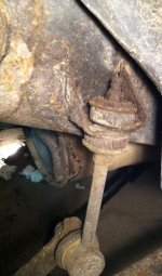
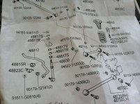
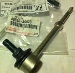
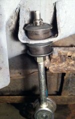
-Remove Stabilizer (sway) Bar. Here is another instance of the rust problems I encountered. I began with the links that attach at the frame rail brackets. The bushings were cracked and dry rotted, and the nut was rusted solid to the link. Even using a small 12mm wrench for the nut, and a small 14mm wrench for the link, both links snapped after applying moderate force. In contrast, the four bolts holding the bushings on the axle housing came out easily using a 12mm socket and a bit of heat.
About this time, I expected what little compression the springs had left to force the axle housing down enough to simply pull them out. Unfortunately, this was not the case - I went to Advanced Auto Parts and rented a set of coil spring compressors and started with the passenger side spring.
-Remove coil springs. Once the passenger side spring was compressed quite a bit, I had a helper stand on the axle housing end to allow the spring to come out the forward side of the axle. I quickly realized that the driver's side spring is a bit more difficult to get the compressors on, due to the lateral control arm bracket being on the rearward side, and the gas tank being so close on the forward side. I got the tools on, and compressed the spring enough so that it would move, but not enough to be applying pressure on the axle housing. Once the rest of the suspension components were removed, the spring could easily be removed once the housing was down.
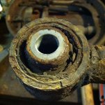
-Cut off all control arm nuts. Again, here is where the project will get even more expensive fast. Besides the stabilizer bar, the only bushings that Toyota offers as replaceable are the ones for the lower control arms. That means that if any of the other bushings are rotted, damaged by trying to burn off the bolts, or simply damaged by the heat used to free up the hardware...you get stuck buying the entire piece. Both upper control arms are over $100each, and so is the lateral one. If you plan to replace these three pieces, or are forced to, I would be stumped to think of why you would NOT replace the hardware anyways...
For me, this project was on a finite timeline and getting too expensive real quick. So I opted to just cut the nuts at the axle housing end for the upper and lateral control arms, and replace the lower control arm bushings all around. While I had the stabilizer bar and lower control arms out I chose to clean them up a bit as well - priming and undercoating with the same as the 3rd member. This also will help me remember what I have replaced, and what I have not, if I ever do need to replace the remaining control arms with included bushings...
By cutting only the axle housing end of the upper and lateral control arm hardware, this also was a great starting point for the new axle housing to be hung in place.
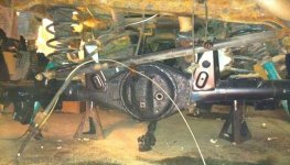
Once the bolts for the control arms were removed, the axle housing was able to be taken out, along with the driver's side spring.
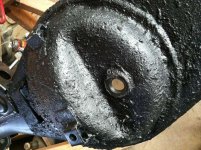
I chose to prime, and use some pretty heavy duty paint-on bed liner material to coat the new axle housing all around the differential cover and those pesky spot welded brackets. The rest of the old housing was in pretty good shape, so I focused on slathering this center section of the new housing.
This is the point where I am at today. More updates on the installation of the new housing to follow, but in the mean time here is a hardware list of what this project has included, along with extra parts for the items I do not intend to completely remove unless I have to:
2: ABS Sensor Bolts - M6 (1.0) x 1.6cm - 10mm socket
4: Brake Cylinder Bolts - M6 (1.0) x 1.0cm - 10mm socket
8: Axle Nuts - M10 (1.25) - 14mm socket
10: 3rd Member Replacement Bolts - M8 (1.25) x 3cm - 12mm socket
2: Lower Shock Bolts - M12 (1.25) x 2cm - 17mm socket
5: Brake Line Clamp Bolts - M8 (1.25) x 1.6cm - 12mm socket
2: Lower Shock Bolts - M12 (1.25) x 2cm - 17mm socket
4: Stabilizer Bar Axle Bolts - M8 (1.25) x 1.6cm - 12mm socket
3: E-Brake Tube Guide and Passenger Housing End Bolts - M8 (1.25) x 2cm - 12mm socket
4: Lower Control Arm Bolts - M12 (1.25) x 10cm - 19mm socket
4: Lower Control Arm Nuts - M12 (1.25) - 19mm socket
2: Lateral Control Arm Bolts - M12 (1.25) x 7.5cm - 19mm socket
2: Lateral Control Arm Nuts - M12 (1.25) - 19mm socket
4: Upper Control Arm Bolts - M10 (1.25) x 9cm - 17mm socket
4: Upper Control Arm Nuts - M10 (1.25) - 17mm socket
-I did not look up what the specs for E-Brake arm bolt (Driver's side axle housing end) was as I re-used this...
-There are also two pins for attaching the E-Brake U-Brackets to the arms on the axle backing plates...
-Lock Washers for all M6, M8, M10, M12 Nuts...
-Flat Washers for all M8, M10, M12 Nuts and Bolts...
I chose to go with Stainless Steel for everything that I could find. The only items I did not get Stainless (mainly due to availability) was the M10 and M12 bolts for the suspension components.
Pictures to follow as well...
My 1998 4Runner SR5 has just over 160K miles, and to my knowledge I am the third owner. The truck has spent most of its life in the rust belt of the northeast where pavement is not black in the winter, but white with all of the road salt and calcium that the DOT dumps on them. Needless to say, this thread is for those of us that call this area home - and to show folks in the other areas of the country how lucky they have it...
To start off with, my 4Runner required rear axle seals - and props to BigFishAllDay for an excellent build thread sticky showing the details of this operation. I used this sticky as a jumping off point for what was to come next - the swap of the rear axle housing.
Please note - This is one expensive task that is forced upon some of us in the rust belt simply due to the fact that the rear differential "pumpkin" cover is not a bolt on item. Toyota in their infinite wisdom decided not only to not make this piece an integrated part of the axle housing, but to simply spot weld two brackets onto it as well - opening the door to two "salt shelves" that will corrode and eventually vibrate causing a hole for the gear oil to leak out of. The following information and the dollar signs will highlight more than anything why Toyota will likely NEVER issue a recall for these issues...
Just the parts:
A new rear axle housing from Toyota was over $1K...
Car Quest rear brake shoes, cylinders, and hardware kit was over $200...
Toyota axle bearings, seals, ABS rotors, retainers, spacers was over $400...
Stabilizer links and bushings for it and the lower control arms were over $200...
Plan on at least $100 in new hardware, and another $100 in consumables for cleaner, gear oil, penetrating oil...and all this is just to start with...more on that later...
First step - Locate the sticky for replacing rear axle seals on this site. Follow those directions for tear down, and buy the parts listed within that thread for reassembly later...
I will add to that sticky by saying that the ABS sensors are a PITA to remove, and at over $200each, one should take great care to not damage them. Unfortunately for us rust belt folks, it is not as simple as a flat blade screwdriver and a bit of prying... Remove the bolt, remove the three closest ABS wire clamps/mounts, hose down the sensor base with penetrating oil, and place a set of channel locks firmly at the base of the sensor. Begin to twist back and forth - rotating the sensor 1/4" in each direction to get it moving. Add additional oil every few rotations to aide the movement. Once you are able to rotate the sensor back and forth without a death grip on the channel locks, rotate so that the tab is above the pad it mounts to.
Use a small pry bar under the tab using the top of the axle housing for leverage to apply a little pressure while continuing to use the channel locks to wiggle the sensor back and forth. Feel free to use additional oil to aide in this process, but this was the only way I could remove my ABS sensors from my housing.
On to where the rear axle sticky ends...
**Plan on replacing almost all hardware, and just about everything else depending on the level of corrosion that your truck has, and how deep your pockets are***
-Begin draining the gear oil from the rear axle housing. Both the drain plug and the fill plug use the same socket size of 24mm. I was lucky and these came out with a little propane from the Bernzo...
-Disconnect the drive shaft from the 3rd member. I replaced all the U-joints and the drive shaft hardware a year ago, so I am unsure of the original bolt specs. The specs for the replacement hardware I used are:
4 Bolts: Stainless Steel M10 (1.00)pitch x 3cm
4 Split Washers: Stainless M10
4 Flat Washers: Stainless M10
4 Lock Nuts: Stainless M10 (1.00)pitch
If memory serves, both the original hardware, and the new hardware both are 14mm. However, it is a tight fit using a socket on the forward side, and only an open ended wrench will fit behind the flange of the 3rd member. NOTE - the bolts can't be much longer than 3cm as the flange for the 3rd member prevents anything much more than the lock nut to fit in there.
-Remove the 3rd member from the axle housing. There are 10 nuts that use threaded studs to secure the 3rd member to the axle housing. You will need a 12mm socket and some heat to remove these. Again, I got lucky and only sheared off two studs in this process - the others came out fairly easy, but most of the time the studs came out along with the nuts. I intend to simply use quality bolts instead of studs for the re-installation.
For whatever reason, my 3rd member was seized onto one of the studs that sheared off flush with it. This one was located in the upper right if you are looking at it from the drive shaft side. It took about an hour of penetrating oil, heating, hammering, and prying to finally free it from the housing.
Once it was out, I chipped off all loose surface rust, then bathed it in a good amount of brake cleaner both inside and out. I also took the opportunity to put a couple thick coats of primer on it before a couple coats of rubberized undercoating. Just be sure to tape off every part of the exposed gears, and keep the holes for the studs clear of what you are spraying...
-Remove all E-Brake, and brake line bolts. These can all be removed with a 12mm socket, and a bit of heat... I saved the clamps for the brake lines, and luckily the rubber brake hose to the axle T was in good shape, and the metal lines came out with a little oil - but I was planning to replace the metal lines so I was not concerned with them breaking.
The only bolt that did not come free was the one holding the E-Brake Guide to the bracket in the center of the differential cover... Go figure... I knew if it was rusty enough to cause the cover to leak gear oil, it was likely fall to pieces in the attempt to remove the bolt that was secured to it.
At this point everything but the suspension components should be removed and/or free from the axle housing.
-Remove the lower Shock bolts. I replaced the shocks a year ago, so the bolts came out without any heat with just a 17mm socket.
-Remove Stabilizer (sway) Bar. Here is another instance of the rust problems I encountered. I began with the links that attach at the frame rail brackets. The bushings were cracked and dry rotted, and the nut was rusted solid to the link. Even using a small 12mm wrench for the nut, and a small 14mm wrench for the link, both links snapped after applying moderate force. In contrast, the four bolts holding the bushings on the axle housing came out easily using a 12mm socket and a bit of heat.
About this time, I expected what little compression the springs had left to force the axle housing down enough to simply pull them out. Unfortunately, this was not the case - I went to Advanced Auto Parts and rented a set of coil spring compressors and started with the passenger side spring.
-Remove coil springs. Once the passenger side spring was compressed quite a bit, I had a helper stand on the axle housing end to allow the spring to come out the forward side of the axle. I quickly realized that the driver's side spring is a bit more difficult to get the compressors on, due to the lateral control arm bracket being on the rearward side, and the gas tank being so close on the forward side. I got the tools on, and compressed the spring enough so that it would move, but not enough to be applying pressure on the axle housing. Once the rest of the suspension components were removed, the spring could easily be removed once the housing was down.
-Cut off all control arm nuts. Again, here is where the project will get even more expensive fast. Besides the stabilizer bar, the only bushings that Toyota offers as replaceable are the ones for the lower control arms. That means that if any of the other bushings are rotted, damaged by trying to burn off the bolts, or simply damaged by the heat used to free up the hardware...you get stuck buying the entire piece. Both upper control arms are over $100each, and so is the lateral one. If you plan to replace these three pieces, or are forced to, I would be stumped to think of why you would NOT replace the hardware anyways...
For me, this project was on a finite timeline and getting too expensive real quick. So I opted to just cut the nuts at the axle housing end for the upper and lateral control arms, and replace the lower control arm bushings all around. While I had the stabilizer bar and lower control arms out I chose to clean them up a bit as well - priming and undercoating with the same as the 3rd member. This also will help me remember what I have replaced, and what I have not, if I ever do need to replace the remaining control arms with included bushings...
By cutting only the axle housing end of the upper and lateral control arm hardware, this also was a great starting point for the new axle housing to be hung in place.
Once the bolts for the control arms were removed, the axle housing was able to be taken out, along with the driver's side spring.
I chose to prime, and use some pretty heavy duty paint-on bed liner material to coat the new axle housing all around the differential cover and those pesky spot welded brackets. The rest of the old housing was in pretty good shape, so I focused on slathering this center section of the new housing.
This is the point where I am at today. More updates on the installation of the new housing to follow, but in the mean time here is a hardware list of what this project has included, along with extra parts for the items I do not intend to completely remove unless I have to:
2: ABS Sensor Bolts - M6 (1.0) x 1.6cm - 10mm socket
4: Brake Cylinder Bolts - M6 (1.0) x 1.0cm - 10mm socket
8: Axle Nuts - M10 (1.25) - 14mm socket
10: 3rd Member Replacement Bolts - M8 (1.25) x 3cm - 12mm socket
2: Lower Shock Bolts - M12 (1.25) x 2cm - 17mm socket
5: Brake Line Clamp Bolts - M8 (1.25) x 1.6cm - 12mm socket
2: Lower Shock Bolts - M12 (1.25) x 2cm - 17mm socket
4: Stabilizer Bar Axle Bolts - M8 (1.25) x 1.6cm - 12mm socket
3: E-Brake Tube Guide and Passenger Housing End Bolts - M8 (1.25) x 2cm - 12mm socket
4: Lower Control Arm Bolts - M12 (1.25) x 10cm - 19mm socket
4: Lower Control Arm Nuts - M12 (1.25) - 19mm socket
2: Lateral Control Arm Bolts - M12 (1.25) x 7.5cm - 19mm socket
2: Lateral Control Arm Nuts - M12 (1.25) - 19mm socket
4: Upper Control Arm Bolts - M10 (1.25) x 9cm - 17mm socket
4: Upper Control Arm Nuts - M10 (1.25) - 17mm socket
-I did not look up what the specs for E-Brake arm bolt (Driver's side axle housing end) was as I re-used this...
-There are also two pins for attaching the E-Brake U-Brackets to the arms on the axle backing plates...
-Lock Washers for all M6, M8, M10, M12 Nuts...
-Flat Washers for all M8, M10, M12 Nuts and Bolts...
I chose to go with Stainless Steel for everything that I could find. The only items I did not get Stainless (mainly due to availability) was the M10 and M12 bolts for the suspension components.
Pictures to follow as well...
Last edited: