Saker’s Ebony Build

The quality on these are second to none.
They thread without issue onto the shafts.
No locking allen set screw or anything of the sort.
Really straight forward!
The only thing I did was to use 8mm bellville washers instead of the split lock washers he includes. Personal preference I suppose.

Yes that link is correct.
It states in that description:
“ CUSTOM ETCHING: Please reply to the order confirmation email with an image or description (text with font) of what you would like. Ideal images are black and white and of high resolution. If no etching is specified via email, a blank shift knob (with no etching) will be shipped.

Popular etching choices include FJ, TRD, TEQ, PRO, 4R, TRAIL, and Distressed American Flag.”

You would just place your selection in the comments when you place the order.

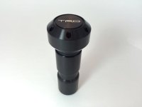
Thanks for the quick response. I did order those (2 left when I ordered, now backordered, so I hope I got in!), and like the order page said, followed up the order confirmation email with my etching request. I wanted TRD, but asked if they could match this, which shows on one of their shifter photos:

Damn this site and photos not showing up...

Like the one on this link:

Black Tundra/5th Gen 4Runner/FJ Cruiser Shift Knob - Automatic Transmi – Ellis Precision
 

Attachments
  • TundraShifter.jpg
    TundraShifter.jpg
    6.9 KB · Views: 2
Last edited:
Joel [MENTION=139559]Ellis Precision[/MENTION] has been making these items for years as well as other stuff.
Absolutely flawless!
 
Last edited:
Thanks again for the Ellis information. I heard back from Joel, and my order has already shipped! I'm impressed.

I ended up ordering the Stealth version.
 
Last edited:
Hello there. I love this thread. The speed of progress is impressive.

Could you share a bit more detail on the wiring (photo?). I'd like to do something similar, but I have no idea where to start wrt the back-up circuit.

Appreciate any help.

November 5, 2020

Installed Rigid Back-Up Lights


These are wired to the trailer light back up circuit.

pm8dDnCkj
 
Hello there. I love this thread. The speed of progress is impressive.

Could you share a bit more detail on the wiring (photo?). I'd like to do something similar, but I have no idea where to start wrt the back-up circuit.

Appreciate any help.

Thanks!!!!!
Prior to purchasing the new T4R, I knew what I wanted to mod (same as previous). Started purchasing my parts and just had to find the time to install once the new 4Runner was purchased.

I don’t have any photos of the process.
The lights are mounted to the bolts on either side of the hitch.
I Found the backup light circuit and the ground on the 7-pin trailer attachment, unplugged, unbolted it & removed it.
Found the wires going to the proper pins (back up circuit) and tied into the wiring to each, ran my wiring to each light and mounted my lights.

So, when you remove that 7pin harness from under the T4R after you know what terminal is the back up circuit and the ground, unwrap the tape locate each wire, connect your new back up light harness wires to the existing 7pin harness wires, insulate or shrink wrap, re-tape and reinstall the harness back on the T4R.

Hope this helps.
 
Thank you - that makes sense. I'll need to dig up a voltmeter it sounds like but that's a good thing to have anyway.

Wish me luck.

Thanks!!!!!
Prior to purchasing the new T4R, I knew what I wanted to mod (same as previous). Started purchasing my parts and just had to find the time to install once the new 4Runner was purchased.

I don’t have any photos of the process.
The lights are mounted to the bolts on either side of the hitch.
I Found the backup light circuit and the ground on the 7-pin trailer attachment, unplugged, unbolted it & removed it.
Found the wires going to the proper pins (back up circuit) and tied into the wiring to each, ran my wiring to each light and mounted my lights.

So, when you remove that 7pin harness from under the T4R after you know what terminal is the back up circuit and the ground, unwrap the tape locate each wire, connect your new back up light harness wires to the existing 7pin harness wires, insulate or shrink wrap, re-tape and reinstall the harness back on the T4R.

Hope this helps.
 
Thanks again for the Ellis information. I heard back from Joel, and my order has already shipped! I'm impressed.

I ended up ordering the Stealth version.
I would love to see the Stealth version compared to Saker's black. PM or new thread I suppose so we don't threadjack (more than I just did).
 
Thank you--I'm guessing the "Stealth" is a bit less sheen than the "Black". I can't really tell from the pics on the Ellis site. They both look great way either way.
Enjoying watching your build come together. I just picked my MGM a few weeks ago and will not be making nearly the progress.
 
Thank you--I'm guessing the "Stealth" is a bit less sheen than the "Black". I can't really tell from the pics on the Ellis site. They both look great way either way.
Enjoying watching your build come together...

Thank you!

The “Stealth” appears to be satin or matte.
You can email Joel, I’m sure he will respond to your questions.
 
The quality on these are second to none.
They thread without issue onto the shafts.
No locking allen set screw or anything of the sort.
Really straight forward!
The only thing I did was to use 8mm bellville washers instead of the split lock washers he includes. Personal preference I suppose.

Yes that link is correct.
It states in that description:
“ CUSTOM ETCHING: Please reply to the order confirmation email with an image or description (text with font) of what you would like. Ideal images are black and white and of high resolution. If no etching is specified via email, a blank shift knob (with no etching) will be shipped.

Popular etching choices include FJ, TRD, TEQ, PRO, 4R, TRAIL, and Distressed American Flag.”

You would just place your selection in the comments when you place the order.

[MENTION=103267]Saker[/MENTION], I am going to pick up a couple of the Belleville washers - is the 8mm the outside or inside diameter?

Thanks,

Gary
 
November 3, 2020

Installed 12V Auxiliary Circuit


pnotGt4Cj

Hi Saker,

This looks great!

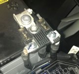
I'm planning something similar but I can't figure out a great way to pull power off the battery terminal on my 2021 ORP. Perhaps this fancy fused terminal connector in my photo may be new? I haven't found even one photo like it using Google image search.

How did you connect the thick red cable supplying your Aux circuit to the battery terminal? I can't tell because it is hidden behind the red plastic protector in your photo. Did you tie in behind the existing 70amp or 250amp fuses? Or did you figure out something that connected your cable to the battery without going though these fuses?

Here's a picture of mine without the protective red cover.

thanks!
 

Attachments

  • battery fused connector.JPG
    battery fused connector.JPG
    66.4 KB · Views: 3
Hi Saker,

This looks great!

I'm planning something similar but I can't figure out a great way to pull power off the battery terminal on my 2021 ORP. Perhaps this fancy fused terminal connector in my photo may be new? I haven't found even one photo like it using Google image search.

How did you connect the thick red cable supplying your Aux circuit to the battery terminal? I can't tell because it is hidden behind the red plastic protector in your photo. Did you tie in behind the existing 70amp or 250amp fuses? Or did you figure out something that connected your cable to the battery without going though these fuses?

Here's a picture of mine without the protective red cover.

thanks!

When I first looked under the red protective cover, I thought the same thing....
How am I going to connect with these fuses!
I told myself I don’t want to jeopardize any part of my electrical system!

I did not go thru those fuses!
When you take the positive cable off, you will notice that all are actually 3 separate parts.
I made a small little copper buss bar with 2 holes drilled in it. It is long enough after it is connected under the positive cable that I can connect my red cable that goes to my auxiliary circuit.

Don’t tie your auxiliary to either of those fuses!
You don’t want to draw power from those.
 
Thanks! I'm definitely wanting to tap the battery directly. I've never yet taken the positive terminal off the battery. I'll do that today and figure out what you're saying about 3 parts and fabricating a buss bar. This topic is probably worth a dedicated thread but I'm still working through my required initial 15 posts. :-/
 
Thanks! I'm definitely wanting to tap the battery directly. I've never yet taken the positive terminal off the battery. I'll do that today and figure out what you're saying about 3 parts and fabricating a buss bar. This topic is probably worth a dedicated thread but I'm still working through my required initial 15 posts. :-/

[MENTION=628603]WakeTime[/MENTION],
These photos may help you a little more.
In the first photo, notice at the end of the crude arrow, there is the small buss bar under the OEM fuse terminal to make the connection to the battery terminal for the cable to the auxiliary circuit.
This way all power to the auxiliary circuit is bypassing those fuses.
Hope these help.

pnKReINSj


pnB7cPk0j
 

Members online

Forum statistics

Threads
278,310
Messages
3,554,080
Members
248,016
Latest member
Advally Service

Trending content

Back
Top