ShakenBake
Member
I really did try finding this answer on my own before posting, so please take it easy on the toast. Yes, I read the Magnuson directions and viewed Tim's supercharger install YouTube video several times.
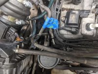
Anyways, this past weekend, I installed a 2nd gen supercharger (black one) on my 1997 SR5 5-speed with the 5vz-fe and I can't quite figure out what to do with the 2 vacuum hoses connected to the power steering unit, nor the 4WD line (I think) that I disconnected when removing the OEM intake manifolds.
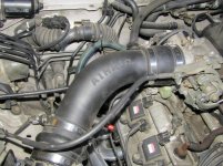
For the power steering lines, one went to the Airaid intake tube (OEM silencer box?) and the other one attached to the upper intake manifold. On page 63/64 of THE Supercharger thread, it seemed like dude capped the line that originally went to the upper intake manifold but re-connected the line going to the Airaid intake tube/silencer box. I'm just not sure if that worked as it should or was the correct routing. Further, why does the power steering need vacuum? It's got a belt driven pump, right? What function does the vacuum serve?
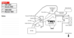
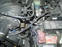
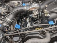
The other vacuum line is a little more confusing to me. It's a small 1/8" hose that used to connect to the most rearward of the 3 fixed, metal vacuum lines that were routed across the top of upper intake manifold. I think it tee'd/y'd into to the fuel pressure regulator vacuum line but I'm not 100% sure. I should have taken a pic. Does this now tee into one of the larger vacuum lines located at the driver's side of the supercharger? If so, it's the one coming off of the evap canister, right?
Anyways, this past weekend, I installed a 2nd gen supercharger (black one) on my 1997 SR5 5-speed with the 5vz-fe and I can't quite figure out what to do with the 2 vacuum hoses connected to the power steering unit, nor the 4WD line (I think) that I disconnected when removing the OEM intake manifolds.
For the power steering lines, one went to the Airaid intake tube (OEM silencer box?) and the other one attached to the upper intake manifold. On page 63/64 of THE Supercharger thread, it seemed like dude capped the line that originally went to the upper intake manifold but re-connected the line going to the Airaid intake tube/silencer box. I'm just not sure if that worked as it should or was the correct routing. Further, why does the power steering need vacuum? It's got a belt driven pump, right? What function does the vacuum serve?
The other vacuum line is a little more confusing to me. It's a small 1/8" hose that used to connect to the most rearward of the 3 fixed, metal vacuum lines that were routed across the top of upper intake manifold. I think it tee'd/y'd into to the fuel pressure regulator vacuum line but I'm not 100% sure. I should have taken a pic. Does this now tee into one of the larger vacuum lines located at the driver's side of the supercharger? If so, it's the one coming off of the evap canister, right?