

rigtec
New member
Hi Tech team,
Lately I've been noticing a ship ton of threads with some of our guys/gals taking the plunge and attempting to do their own auto electric install work themselves; this I'm excited about! One of the things I love the most about life is the ability to learn new things ...everyday! And I love being around smart people who love learning as well; they inspire me! Now I realize that some of you may have some background in electrical systems. But I also know that a few here have said that they may be a bit squeamish or timid about getting too far out there because they may not understand the principles and the theory behind electrical systems, and so have been holding back wrt these systems as a result.
Well the purpose of this thread is to introduce those of you who may be unfamiliar with some of the basic components and explain just how they work and exactly what they're for. I plan to keep it very simple and basic so all reading this post can understand everything discussed here. For those of you who are already experts in electrical systems who may be contributing to this thread, please remember that the focus should be for those who may be just beginning (electrical 101) so I ask you to please keep your contributions on the 101 level out of respect to those who would like to learn some of what you may already know, okay?!
Below I have drawn a sketch of a basic LED light harness and it's wiring scheme that ends at it's load which is a LED-lightbar, "see below":

Try if you can, NOT to focus on where I tapped into the 12V power source to energize the AOB switch, it's coming from the battery via the IGN SWITCH. I deliberately excluded certain electrical components (D/S Fusebox) to introduce the basic parts of the system for the benefit of those who may be seeing an aftermarket wiring plot on paper for the very first time. Also, I will admit that I don't have any advanced artistic programs on my laptop; it doesn't even have a touch screen or the ability to draw lines directly on the screen so I drew the basic components on paper like back in the days of old when all you had was a pencil, paper and an eraser.
Looking at the simple plot above there are six main components, we'll start with the battery, which then is wired to the vehicle's (over-simplified) ignition switch. The current leaves the battery and enters the ignition switch at the bottom. When the sw is turned on the power exits at the top via IG1 (Accessory SW) and enters our AOB light switch at the bottom labeled 12V IN: my illustrations are not physically correct (regarding top or bottom; that is just for the ability of keeping the wires from crossing each other, and for the simplicity of reading it with more clarity).
From there, when the switch is in the on position, the current will pass through to the output term, energizing the on status indicator at the same time... see the GREEN led near the top; one of it's traces (wires) is connected to the terminal that says output and the other trace is connected to the ground. If you follow the output from the switches output, it goes to the relay's terminal marked 85. The way this works, terminals #85 and 86 are connected to a small coil (spool) of wire that will generate a magnetic field when connected to a 12V power source.
So we call that a Trigger, which means that when we energize the coil another internal mechanical part, the main contacts are pulled together. This set of contacts are numbered #30 (or common), 87A the normally closed electrical path (means the coil does not need to be connected to power for this circuit to pass through to that output. And then there's #87, a set of normally opened set of contacts; which will not allow current to pass through until power is at the coil. This is the one that is used to energize the load wire; which in this case is connected to an LED lightbar!
Following me so far? I do plan to introduce additional information to this thread later on at some point, but not at this time; think that's enough for you to think about for now! I will however present a few photos of the actual components... you do still like looking at pictures don't you lol!
THIS IS THE STOCK STYLE SWITCH THAT COMES WITH MOST AFTERMARKET HARNESSES

"We usually just cut them off the harness and add a factory style switch" like this great thread... https://www.google.com/url?q=http:/...ds-cse&usg=AFQjCNECJhemlyQNzC1o9xJBvGwUE5uoQg Courtesy of [MENTION=81322]barryhiram[/MENTION] !" ...thanks Barry for posting that well detailed, well explained posting; if it weren't for you and that thread I'd still be cutting into lower bolster airbag panel to add light switches, I ruined the original one so I replaced it with another factory lower airbag panel $110 bucks on ebay!
MAIN ELECTRICAL PARTS NEEDED "Less the IGN switch"

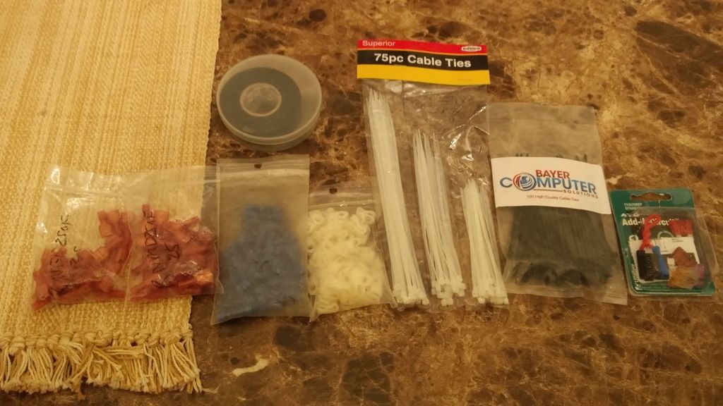
AND LASTLY, SOME ELECTRICAL STOCK TO HELP WITH KEEPING IT NEET! forgot to photograph the 1/2" split loom insulation... comes in 10', 25', 50' and 100' rolls on amazon!
Well that's it for the moment... but I hope that you will begin a dialog about aftermarket electrical installs that you are hoping to do or perhaps there are still things that I've neglected to explain or wasn't very clear on some parts of this post; I'd be happy to talk about things or to answer any questions that might be looming around out there. If you can't ask me online, feel free to shoot me a PM, I'll get back to you asap! 'Best to you'!
rig
Lately I've been noticing a ship ton of threads with some of our guys/gals taking the plunge and attempting to do their own auto electric install work themselves; this I'm excited about! One of the things I love the most about life is the ability to learn new things ...everyday! And I love being around smart people who love learning as well; they inspire me! Now I realize that some of you may have some background in electrical systems. But I also know that a few here have said that they may be a bit squeamish or timid about getting too far out there because they may not understand the principles and the theory behind electrical systems, and so have been holding back wrt these systems as a result.
Well the purpose of this thread is to introduce those of you who may be unfamiliar with some of the basic components and explain just how they work and exactly what they're for. I plan to keep it very simple and basic so all reading this post can understand everything discussed here. For those of you who are already experts in electrical systems who may be contributing to this thread, please remember that the focus should be for those who may be just beginning (electrical 101) so I ask you to please keep your contributions on the 101 level out of respect to those who would like to learn some of what you may already know, okay?!
Below I have drawn a sketch of a basic LED light harness and it's wiring scheme that ends at it's load which is a LED-lightbar, "see below":

Try if you can, NOT to focus on where I tapped into the 12V power source to energize the AOB switch, it's coming from the battery via the IGN SWITCH. I deliberately excluded certain electrical components (D/S Fusebox) to introduce the basic parts of the system for the benefit of those who may be seeing an aftermarket wiring plot on paper for the very first time. Also, I will admit that I don't have any advanced artistic programs on my laptop; it doesn't even have a touch screen or the ability to draw lines directly on the screen so I drew the basic components on paper like back in the days of old when all you had was a pencil, paper and an eraser.
Looking at the simple plot above there are six main components, we'll start with the battery, which then is wired to the vehicle's (over-simplified) ignition switch. The current leaves the battery and enters the ignition switch at the bottom. When the sw is turned on the power exits at the top via IG1 (Accessory SW) and enters our AOB light switch at the bottom labeled 12V IN: my illustrations are not physically correct (regarding top or bottom; that is just for the ability of keeping the wires from crossing each other, and for the simplicity of reading it with more clarity).
From there, when the switch is in the on position, the current will pass through to the output term, energizing the on status indicator at the same time... see the GREEN led near the top; one of it's traces (wires) is connected to the terminal that says output and the other trace is connected to the ground. If you follow the output from the switches output, it goes to the relay's terminal marked 85. The way this works, terminals #85 and 86 are connected to a small coil (spool) of wire that will generate a magnetic field when connected to a 12V power source.
So we call that a Trigger, which means that when we energize the coil another internal mechanical part, the main contacts are pulled together. This set of contacts are numbered #30 (or common), 87A the normally closed electrical path (means the coil does not need to be connected to power for this circuit to pass through to that output. And then there's #87, a set of normally opened set of contacts; which will not allow current to pass through until power is at the coil. This is the one that is used to energize the load wire; which in this case is connected to an LED lightbar!
Following me so far? I do plan to introduce additional information to this thread later on at some point, but not at this time; think that's enough for you to think about for now! I will however present a few photos of the actual components... you do still like looking at pictures don't you lol!
THIS IS THE STOCK STYLE SWITCH THAT COMES WITH MOST AFTERMARKET HARNESSES

"We usually just cut them off the harness and add a factory style switch" like this great thread... https://www.google.com/url?q=http:/...ds-cse&usg=AFQjCNECJhemlyQNzC1o9xJBvGwUE5uoQg Courtesy of [MENTION=81322]barryhiram[/MENTION] !" ...thanks Barry for posting that well detailed, well explained posting; if it weren't for you and that thread I'd still be cutting into lower bolster airbag panel to add light switches, I ruined the original one so I replaced it with another factory lower airbag panel $110 bucks on ebay!
MAIN ELECTRICAL PARTS NEEDED "Less the IGN switch"

AND LASTLY, SOME ELECTRICAL STOCK TO HELP WITH KEEPING IT NEET! forgot to photograph the 1/2" split loom insulation... comes in 10', 25', 50' and 100' rolls on amazon!

Well that's it for the moment... but I hope that you will begin a dialog about aftermarket electrical installs that you are hoping to do or perhaps there are still things that I've neglected to explain or wasn't very clear on some parts of this post; I'd be happy to talk about things or to answer any questions that might be looming around out there. If you can't ask me online, feel free to shoot me a PM, I'll get back to you asap! 'Best to you'!
rig
Last edited:


