Transmission pan adapter for temp gage?

Pillar would work too, I considered it but had already spent boat loads of money on other stuff so I just decided to mount it on the center console near the shifter.

The only catch is, I had to use a hole saw and drill a spot for it. I would just get a pillar mount since that sounds like what you want anyway.

I think Tim asked about where the wires were run. I tapped into the headlight switch wire I believe by steering column, if you look back on that post I made it says which color the wire is. The glowshift gauge I bought dims when you turn on the headlights which is nice. For the signal wires (if installed on shift console) I just fed them back and up and over (I believe, maybe under) the steering console and fed it to the boot on the drivers side firewall (where the massive wire loom goes through) and snaked it around the engine bay to the T fitting. I zip tied everything to secure it so it does break or get messed up.

Good luck

Thanks! And for Tim/others, the dimmable illumination wires in the 4Runners are always G for hot and W-G for ground. There are plenty of them routed behind dash bezel and switches, just pick one.
 
Thanks! And for Tim/others, the dimmable illumination wires in the 4Runners are always G for hot and W-G for ground. There are plenty of them routed behind dash bezel and switches, just pick one.

Ok, just to let you and others know on this thread, I'm an Electrical Tard. My experience with auto electrical is very very minimal but I'm willing to learn.

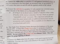
I just bought a Max Tow gauge via Amazon. It had better reviews than the Auto Meter. To wire the meter, it has 4 wires (white, red, orange and black). The black is easy because I just have to connect that to a ground somewhere. Where to tap the other ones into are what confuses me. The white is suppose to connect to a 12 volt ignition (switched source). The red is is suppose to a 12 volt constant (un-switched source). The orange is suppose to connect to a 12 volt positive (headlamp source).

Here's a copy of the instructions. It's steps 4-6 I need to figure out. What would be a switched source to connect to? What would be an un-switched source to connect to? And, what would be the positive headlamp source to connect to? What kind of connector do you use to tap into these wires? Based off what you said above, it sounds like I could hook up the orange wire to one under the dash with a "G" and then connect the black wire to one under the dash with a "W-G"?

Sorry for highjacking this thread but I think anyone finding this thread would appreciate the extra detail I'm asking for and some pictures of what you're talking about would be awesome if you have them. I plan on making a video of the install so I want to pass on accurate information. Thanks!

[MENTION=138943]thegipper[/MENTION] [MENTION=143526]theesotericone[/MENTION]


20180106_083800.jpg
 

Attachments

  • 20180106_083800.jpg
    20180106_083800.jpg
    133.4 KB · Views: 231
Last edited:
It's steps 4-6 I need to figure out. What would be a switched source to connect to? What would be an un-switched source to connect to? And, what would be the positive headlamp source to connect to? What kind of connector do you use to tap into these wires? Based off what you said above, it sounds like I could hook up the orange wire to one under the dash with a "G" and then connect the black wire to one under the dash with a "W-G"?

Tim,

It's difficult to tell without knowing what they are doing with the wires on the gauge side. Some are obvious - White to switched power (so the gauge is only on when the engine is on); and Black for ground.

But they are doing something funky with the Red (I don't understand why the gauge would need a constant 12V supply). Unless it's for some type of memory, like for the dimming setting.

Same for the Orange, it is NOT (as far as I can see) the same as the G on our trucks, which is dimmable illumination. Instead, they are using the Orange wire to sense when the headlights are on, and then they dim the gauge with internal logic. So you can't connect the Orange to a dimmable source like our G, you have to find a headlight wire before the dimmer.

I'd call them and ask them to explain these functions a bit better.

Failing that, just do what they say - connect W to some fuse that is switched (or tap off the cigarette lighter, it's switched), connect R to constant 12V (I bet there is some wire behind the console that is 12V constant, e.g. the clock), B to ground, and O to some wire in the headlight circuit before the dimmer (that's the part I'd have to research to find). All of these are going to be extremely low amperage, so I would not worry about overloading any circuit.

If you're in a bind, please let us know and I'll dig up the wiring diagram and see where to tap the O wire into.

The gauge is neat, I've never seen an electrical gauge with 270 deg sweep, and the digital display is neat. I just got the Autometer gauge, which I am planning to install soon.
 
Tim,

It's difficult to tell without knowing what they are doing with the wires on the gauge side. Some are obvious - White to switched power (so the gauge is only on when the engine is on); and Black for ground.

But they are doing something funky with the Red (I don't understand why the gauge would need a constant 12V supply). Unless it's for some type of memory, like for the dimming setting.

Same for the Orange, it is NOT (as far as I can see) the same as the G on our trucks, which is dimmable illumination. Instead, they are using the Orange wire to sense when the headlights are on, and then they dim the gauge with internal logic. So you can't connect the Orange to a dimmable source like our G, you have to find a headlight wire before the dimmer.

I'd call them and ask them to explain these functions a bit better.

Failing that, just do what they say - connect W to some fuse that is switched (or tap off the cigarette lighter, it's switched), connect R to constant 12V (I bet there is some wire behind the console that is 12V constant, e.g. the clock), B to ground, and O to some wire in the headlight circuit before the dimmer (that's the part I'd have to research to find). All of these are going to be extremely low amperage, so I would not worry about overloading any circuit.

If you're in a bind, please let us know and I'll dig up the wiring diagram and see where to tap the O wire into.

The gauge is neat, I've never seen an electrical gauge with 270 deg sweep, and the digital display is neat. I just got the Autometer gauge, which I am planning to install soon.

So it sounds like the wiring for the auto meter is more straight forward than the one I bought. I forgot about my friend Mikey who did the V8 Swap. He's well-versed in auto electrical so I hit him up for some help. If wiring that Max Tow gauge is more work than it's worth, I'll just buy the Auto Meter one.

When you wire yours in, could you take some pictures to share with the rest of us?

Thanks!
 
For grins and giggles I just took some trans temp readings with my no-touch infrared thermometer and compared to Torque Pro. Drove for about 30 mins and pulled over and left it idling. All readings were taken more than once and were within 2-3°
The readings below are the average, or numbers seen most:

Torque Pro: 145°

Pan: 145°

Trans body and output line to rad cooler: 157°

Rad cooler output to aux cooler: 111° (same at aux cooler coz not moving)​

I guess Toyota is reading the temp near the pan because the readings around the pan were within consistently 1-2° of Torque Pro and I suppose these values could radically change and while driving under various conditions (load)

None of this matters, just sharing


It matters. It proves that I put my tee and temp probe in the hottest part of my system. If those numbers are close to what most rigs read that means my 195 temps when wheeling steep grades are closer to 185 in the pan. Thanks for verifying those numbers for my lazy ass.
[MENTION=198376]4Runner4Leon[/MENTION]

It needs constant power to keep memory settings, specifically LED color in this case. I agree it's not ideal but your stock and aftermarket radios keep memory using the same system.
[MENTION=120071]mtbtim[/MENTION]

Speaking of head units, it has all you need to tap into to wire your gauge. I'll link the wiring diagram from 12volt.com. Bookmark the site if you plan on learning about 12V electrical systems. It's helped a lot of folks overcome the "tard" badge. lol

Use the chart to tap into the wires you need. Some will say to t-tap. Don't. Some will say only solder. I'd agree but if you can't solder or don't own the equipment a simple barrel connector will work fine as long as it's crimped properly. Go the extra mile and put some shrink tubing around the barrels.

https://www.the12volt.com/installbay/stereodetail/2026.html
 
Acutemp adapter. I did read somewhere the temps were about 10deg cooler than inside the pan?


Genos Garage (Diesel)


281_2297_large.jpg


I have been searching for this exact type of solution. Thank you for posting it. On another note, I wonder if adding some thermal paste like the kind used in computer processors would be beneficial for measuring heat by conduction.
 
It matters. It proves that I put my tee and temp probe in the hottest part of my system. If those numbers are close to what most rigs read that means my 195 temps when wheeling steep grades are closer to 185 in the pan. Thanks for verifying those numbers for my lazy ass.

[MENTION=198376]4Runner4Leon[/MENTION]

It needs constant power to keep memory settings, specifically LED color in this case. I agree it's not ideal but your stock and aftermarket radios keep memory using the same system.

[MENTION=120071]mtbtim[/MENTION]

Speaking of head units, it has all you need to tap into to wire your gauge. I'll link the wiring diagram from 12volt.com. Bookmark the site if you plan on learning about 12V electrical systems. It's helped a lot of folks overcome the "tard" badge. lol

Use the chart to tap into the wires you need. Some will say to t-tap. Don't. Some will say only solder. I'd agree but if you can't solder or don't own the equipment a simple barrel connector will work fine as long as it's crimped properly. Go the extra mile and put some shrink tubing around the barrels.

https://www.the12volt.com/installbay/stereodetail/2026.html

Thanks for sharing this. Looks like the wiring for the stereo can handle everything except the dimmable function. I'd have to run that wire possibly to the headlight switch in the steering column?
 
So it sounds like the wiring for the auto meter is more straight forward than the one I bought.

It is - it's just one wire to sensor, one wire to ground, and one wire to the illumination source (G in our trucks). But I don't think that the Max Tow wiring is rocket science, just requires a bit more research.

When you wire yours in, could you take some pictures to share with the rest of us?

Thanks!

Sure, though I think others have already done it, and I may not get around to doing mine for a couple of weeks still.
 
Thanks for sharing this. Looks like the wiring for the stereo can handle everything except the dimmable function. I'd have to run that wire possibly to the headlight switch in the steering column?


The green illumination wire will dim when the headlights are turned on. Use that unless you really need fine tune dimmable control. I haven't tried to tap anything into the adjustable dimmer circuit that controls the brightness of your gauge cluster. Things can go wrong in a hurry playing with that.
 
The green illumination wire will dim when the headlights are turned on. Use that unless you really need fine tune dimmable control. I haven't tried to tap anything into the adjustable dimmer circuit that controls the brightness of your gauge cluster. Things can go wrong in a hurry playing with that.

Awesome. Ok, I've got one more question. I'm trying to source a matching interior trim paint. My interior from the original window sticker says Oak. But, the interior has two different colors. The dash and parts of the door panel are a darker oak color and the pillar trims are a lighter oak color. I did a search for an interior auto paint and found a thread on TTora. Some dudes sent in a sample to SEM and got a custom paint color to match the trim. It's custom color #0176. Here's a link: Sem color coat

I was about to order it but they want $30 for the paint and another $15 for shipping. That's a pretty steep price to pay just so you can match your a-pillar gauge pod. Does anyone else have a more affordable solution to matching the interior paint?
 
Awesome. Ok, I've got one more question. I'm trying to source a matching interior trim paint. My interior from the original window sticker says Oak. But, the interior has two different colors. The dash and parts of the door panel are a darker oak color and the pillar trims are a lighter oak color. I did a search for an interior auto paint and found a thread on TTora. Some dudes sent in a sample to SEM and got a custom paint color to match the trim. It's custom color #0176. Here's a link: Sem color coat

I was about to order it but they want $30 for the paint and another $15 for shipping. That's a pretty steep price to pay just so you can match your a-pillar gauge pod. Does anyone else have a more affordable solution to matching the interior paint?

Tim,

For the lighter Oak trim (pillars, overhead console) I went with SEM's Medium Prairie Tan. It was a very close match, see below the color of the Homelink (which I painted) vs the overhead console which is OEM:


For the darker trim, I'm not sure what to use, I'd love to have someone else be the guinea pig (gets expensive at $15/can :)).
 
Last edited:
Tim,

For the lighter Oak trim (pillars, overhead console) I went with SEM's Medium Prairie Tan. It was a very close match, see below the color of the Homelink (which I painted) vs the overhead console which is OEM:


For the darker trim, I'm not sure what to use, I'd love to have someone else be the guinea pig (gets expensive at $15/can :)).

Thanks. I just ordered a can.

Ok, sounds like I can't use the green stereo wire to connect to the orange wire.
I figure my buddy Mikey can figure out where to hook up that orange wire for the dimming feature. If not, I'll just won't connect it since the directions says you can omit hooking up this wire. The Max Tow gauge seems like more of a hassle but I like it's read-out better than the Auto Meter, especially with the digital display included.

When I get around to it, we'll shoot a video so others can benefit from it. For the video, I'd like to be able to tell people how they would hook up the Auto Meter Gauge if they choose to go that route. It sounds like you will utilize the Blue/Yellow or Blue/Black for the Constant 12V, the Gray for the Switched 12V, and the Green wire for the lighting of the gauge? Will you use the Brown for the ground or just hook up the ground wire to a screw that connects up to the body?

I appreciate all the help Fellers!
 
We're really getting off-topic from the original thread, but that's OK with me :).

T
Ok, sounds like I can't use the green stereo wire to connect to the orange wire.

Tim, I just looked at the wiring diagram, and I am 99.9% sure that you can connect that Orange wire to a G wire. My understanding is that the G wire gets full 12V from the battery when the headlight switch is on, which is exactly what Max Tow wants. The dimming takes place on the downstream side of the bulbs, on the grounding side (W-G) - that's where the rheostat is located. Have a look below if you want to check for yourself.

So I'd find a G wire, check that it gets 12V with the headlight switch on, no matter what the rheostat is set to, and if so, splice the Orange wire to it. What could possibly go wrong??


Last edited:
We're really getting off-topic from the original thread, but that's OK with me :).


Tim, I just looked at the wiring diagram, and I am 99.9% sure that you can connect that Orange wire to a G wire. My understanding is that the G wire gets full 12V from the battery when the headlight switch is on, which is exactly what Max Tow wants


That's what I've been trying to tell you. Everyone of my after market switches, radio, and trans temp gauge are wired to Green for dimming when the lights come on. It works. lol
 
That's what I've been trying to tell you. Everyone of my after market switches, radio, and trans temp gauge are wired to Green for dimming when the lights come on. It works. lol

Ah, OK. I read what you said earlier ("The green illumination wire will dim when the headlights are turned on"), and interpreted it incorrectly I guess, because the whole point is that the green wire does NOT dim, it's always 12V when the headlights are on. The W-G wire is the one that has the rheostat.

Glad we figured it out!
 
Last edited:
We're really getting off-topic from the original thread, but that's OK with me :).


Tim, I just looked at the wiring diagram, and I am 99.9% sure that you can connect that Orange wire to a G wire. My understanding is that the G wire gets full 12V from the battery when the headlight switch is on, which is exactly what Max Tow wants. The dimming takes place on the downstream side of the bulbs, on the grounding side (W-B) - that's where the rheostat is located. Have a look below if you want to check for yourself.

So I'd find a G wire, check that it gets 12V with the headlight switch on, no matter what the rheostat is set to, and if so, splice the Orange wire to it. What could possibly go wrong??

Hey Leon, I apologize for taking your thread on a detour. I was just starting my research on how to install an aftermarket transmission temperature gauge and came across your thread. I figured you and others commenting on the thread would be able to answer all my questions, and I was right. I appreciate all the help you and [MENTION=143526]theesotericone[/MENTION] gave me on this. I now feel confident on how to tackle this job. I'm still going to let my friend Mikey help me do the wiring because I know he'll be able to recommend the best type of connectors to splice into the existing wiring.

Thanks again!
 

Members online

No members online now.

Forum statistics

Threads
278,315
Messages
3,554,104
Members
248,016
Latest member
Advally Service

Trending content

Back
Top