I am connecting up the "raptor style" LED's in the grill of my 2015 4Runner, and need to find a 12V+ ignition switched power wire, preferably in the drivers side kick panel. Does anybody happen to know of one that is safe to tap into? I looked around with the voltmeter, and found a pink wire that was on only with ignition, after tapping into it the right turn signal was stuck on, so not all wires with 12V are safe to use (I even tried putting a diode inline to isolate it). The FA1 connector is easily accessible, but I am not sure if it contains a useful wire for this.

You are using an out of date browser. It may not display this or other websites correctly.
You should upgrade or use an alternative browser.
You should upgrade or use an alternative browser.
12V+ Ignition switched power wire
- Thread starter MorphiasX
- Start date
Register to hide this ad

RysiuM
New member
I had the same question not for 2015 but 2012 SR5 installing Osram LED/FOG lights. I believe I did the cleanest job ever possible not by screwing up existing wiring but I put my own fuse in fuse box (inside driver's kick panel) and add pigtail wire to empty slot in one of ECU plugs. See how I did it in my truck, and with a little luck you may be able to do something similar.
http://www.toyota-4runner.org/5th-gen-t4rs/208430-osram-ledfog101-installed-2012-sr5.html#post2183849
http://www.toyota-4runner.org/5th-gen-t4rs/208430-osram-ledfog101-installed-2012-sr5.html#post2183849

rigtec
New member
I am connecting up the "raptor style" LED's in the grill of my 2015 4Runner, and need to find a 12V+ ignition switched power wire, preferably in the drivers side kick panel.
Hi MorphiasX,
I understand what your goal is however, these 4Runners employ what's known as a 'Ground-side Switch' system where most of our electrical systems are "HOT AT ALL TIMES". So instead of the switches providing voltage to the accessories (as in conventional systems), they provide a ground to the accessories thus completing the circuit. Your best option may simply be to install a fused, designated line from the battery to your new lighting system, a relay to control it, and an aftermarket, interior switch on the dash for your convenience.
Is this a kit that comes with a harness and integrated relay?
Last edited:
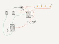
I am aware of the ground switched system, I am actually not powering the lights from the 12V+ connection, I built a circuit consisting of two relays and two diodes that will allow the LED lights I added to be on with the DRL and the parking lights, but will turn off when the stalk switch is in the OFF position. The last part of the circuit I need is to provide 12V+ switched power to the relays, I know that if I need, I can tap into the radio connection or the cigarette lighter connection, but I was trying to avoid tearing apart the center dash for one connection.
What I found was that the wire for the DRL (Connector FA1 Pin 17) supplied 12V+ when the lights were OFF, not ON. So I built a circuit to work with that. I will attach a diagram I drew up, very cheesy drawing, but accurate.
No kit or harness, all custom made.
What I found was that the wire for the DRL (Connector FA1 Pin 17) supplied 12V+ when the lights were OFF, not ON. So I built a circuit to work with that. I will attach a diagram I drew up, very cheesy drawing, but accurate.
No kit or harness, all custom made.
Attachments
Last edited:
RysiuM
New member
I understand what your goal is however, these 4Runners employ what's known as a 'Ground-side Switch' system where most of our electrical systems are "HOT AT ALL TIMES". So instead of the switches providing voltage to the accessories (as in conventional systems), they provide a ground to the accessories thus completing the circuit. Your best option may simply be to install a fused, designated line to your new lighting system, a relay to control it, and an aftermarket, interior switch on the dash for your convenience.
That's right, I did not see you were trying to tap into ignition switch - don't do it. As a matter of fact don't tap into any switch as most of switches do not provide power, but provide a signal to ECU - like "rigtec" wrote, simply grounding the ECU input signal. So by tapping to the 'hot" side of the switch you will not get 12V power, but you will interfere with ECU making it "go crazy".
However it is safe to tap into any 12V fused wire that is going from any relay turned on by ECU when ignition is ON. Again, I don't know 2015 diagram - I use only diagrams for 2010 published on the forum, so I can't say for sure which wire would it be, but in 2010 there are 5 relays turned on by ignition switch protected by different fuses (different Amps). If you have that possibility, chcek the internal diagram of "Driver Side J/B Assembly Inner Circuit" - this one has all relays and connectors identified. Just keep in mind that fuse protects the wire, not the device. So if the harness for your lights has thin wires don't connect them behind big Amp fuse.
RysiuM
New member
What I found was that the wire for the DRL (Connector FA1 Pin 17) supplied 12V+ when the lights were OFF, not ON. So I built a circuit to work with that. I will attach a diagram I drew up, very cheesy drawing, but accurate.
As for FA1 pin 17, if it behaves like you write it may be a "logic signal" level, not power level. I don't see that pin on 2010 diagram, but the same behavior is in 2010 for DRL signal going from ECU to flasher - High (12V) is when DRL is OFF, and ground level when DRL is ON. This is consistent with behavior of switches in 4R which are closing the signal wire to ground: when closed the signal level is Ground.
Now saying that I suspect that you can't power anything of that wire - not even the relay. It may screw up the ECU and make it go nuts. I don't recommend to connect anything to any wire in 4R unless you know where it is coming from and where it is going for which knowing the wiring diagram is almost a must. Unfortunately there is a significant difference in front light design between 2014 and 2010 (even both are called 5th gen) making 2010 diagram unusable for 2014 models.
As for FA1 pin 17, if it behaves like you write it may be a "logic signal" level, not power level. I don't see that pin on 2010 diagram, but the same behavior is in 2010 for DRL signal going from ECU to flasher - High (12V) is when DRL is OFF, and ground level when DRL is ON. This is consistent with behavior of switches in 4R which are closing the signal wire to ground: when closed the signal level is Ground.
Now saying that I suspect that you can't power anything of that wire - not even the relay. It may screw up the ECU and make it go nuts. I don't recommend to connect anything to any wire in 4R unless you know where it is coming from and where it is going for which knowing the wiring diagram is almost a must. Unfortunately there is a significant difference in front light design between 2014 and 2010 (even both are called 5th gen) making 2010 diagram unusable for 2014 models.
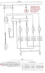
I will attach the screenshot from a diagram that I referenced from another thread, not sure what year it is for, I think it might be a 2010. Using the voltmeter though I can confirm that the light green wire in FA1 Pin 17 does relate to the DRL.
I still have not been able to get it to work properly pulling from that wire though, there has to be a place in the circuit that can be used to atleast control a relay.
Attachments
RysiuM
New member
I will attach the screenshot from a diagram that I referenced from another thread, not sure what year it is for, I think it might be a 2010.
No, this is 2013+ diagram, where DRL are done via Hheadlights (2010 have DRL via front blinkers - see the 2010 diagram below).
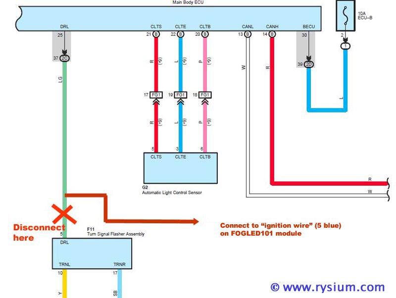
However the ECU logic is exactly the same as in 2010- signal from ECU (pin 37 2C) is the same in your diagram as in 2010 diagram. The difference is that in 2010 model 37 2C is connected to pin 5 in flasher unit, but in 2014+ it is connected to pin 2 in DRL relay.
So in short, pin 17 FA1 (which is the same as pin 37 2C in ECU) does not carry any power, just logical level. Don't plug anything to it that might take power or ECU and/or DRL will go nuts.
Now, I am not clear what effect do you want to achieve? When your "raptor" lights should be On and when Off?
No, this is 2013+ diagram, where DRL are done via Hheadlights (2010 have DRL via front blinkers - see the 2010 diagram below).
However the ECU logic is exactly the same as in 2010- signal from ECU (pin 37 2C) is the same in your diagram as in 2010 diagram. The difference is that in 2010 model 37 2C is connected to pin 5 in flasher unit, but in 2014+ it is connected to pin 2 in DRL relay.
So in short, pin 17 FA1 (which is the same as pin 37 2C in ECU) does not carry any power, just logical level. Don't plug anything to it that might take power or ECU and/or DRL will go nuts.
Now, I am not clear what effect do you want to achieve? When your "raptor" lights should be On and when Off?
I am trying to have the LED's on with all light functions but be able to turn off with the stalk OFF position. I currently have it connected to the parking light wire, so it is on with all light positions except DRL. I really just need a way to trigger a relay when the DRL's come on.
RysiuM
New member
I really just need a way to trigger a relay when the DRL's come on.
I can't tell in 2014 if the logic is the same or not but this is how it works in my 2012 (DRL are front blinkers):
Stick position Off - DRL Off
Stick position DRL - DRL On (when parking brake is released and engine running)
Stick position Tail - DRL On (when parking brake is released and engine running)
Stick position Head - DRL Off
Tail lamps are ON when stick position is on Tail or Head regardless of Ignition position.
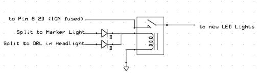
Unfortunately you don't have access to DRL power in the cabin - I think DRL Relay is in the engine compartment. That makes it difficult. But if you need that functionality you can do the following (not exactly the cleanest solution):
power your LED via your own relay and from the fuse when ignition is On
use two wires with diode in each ire to turn on the relay - one from marker (tail) light, the other from DRL light (either side). There is no access to DRL other than splitting the wire going between DRL relay and the headlight (I hate splitting wires).
This way you will have your LED only On when the engine is running (Ignition is ON) and stick is on any position other than OFF.
RysiuM
New member
I had thought about tapping into the high beam bulb positive wire to power the relay, I may have to go that route.
I was thinking about something like that. Diodes are not critical - 50V 1A will be more than enough (1N4001). You will need micro fuse for your light that will fit into fuse box in driver side kick panel (similar to what I did for my DRL)
Attachments
Last edited:

CactusHugr
New member
I know this is an old post...
But I was searching myself for a 12v+ lead, ignition on only, under dash. This post pops up in google so I'll use it to spread my solution.
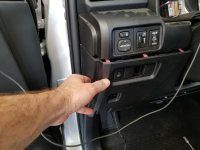
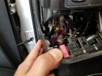
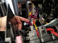
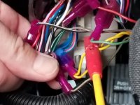
Driver side knee bolster needs to be removed, but behind the push botton panel on the left I've found where the hacks at the dealership tapped into the wiring for the shitty alarm they wanted to sell me. One of those taps is a fairly thick little blue with red wire that's only hot with ignition on. Note, this isn't accessory on, only ignition.
I'm using it because if something goes wrong it's the dealers fault only!
Not sure what that wire normally powers - no wiring diagrams yet. Mine is 2017.
But I was searching myself for a 12v+ lead, ignition on only, under dash. This post pops up in google so I'll use it to spread my solution.
Driver side knee bolster needs to be removed, but behind the push botton panel on the left I've found where the hacks at the dealership tapped into the wiring for the shitty alarm they wanted to sell me. One of those taps is a fairly thick little blue with red wire that's only hot with ignition on. Note, this isn't accessory on, only ignition.
I'm using it because if something goes wrong it's the dealers fault only!
Not sure what that wire normally powers - no wiring diagrams yet. Mine is 2017.
Attachments

GearJunkie88
New member
But I was searching myself for a 12v+ lead, ignition on only, under dash. This post pops up in google so I'll use it to spread my solution.
This may even be easier:
https://www.rockcreekoverland.com/si...ghts-in-grille
CactusHugr
New member
Link isn't working...
GearJunkie88
New member

Charlievee
Senior Member
That right there is what I want to avoid.But I was searching myself for a 12v+ lead, ignition on only, under dash. This post pops up in google so I'll use it to spread my solution.
Driver side knee bolster needs to be removed, but behind the push botton panel on the left I've found where the hacks at the dealership tapped into the wiring for the shitty alarm they wanted to sell me. One of those taps is a fairly thick little blue with red wire that's only hot with ignition on. Note, this isn't accessory on, only ignition.
I'm using it because if something goes wrong it's the dealers fault only!
Not sure what that wire normally powers - no wiring diagrams yet. Mine is 2017.

ElectroBoy
Banned
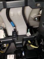
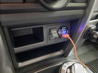
anyone want to take a guess on which one is hot? green or white striped black? I have looked everywhere for my multimeter and cant seem to find it. this is for the center console cig lighter
You really need a multimeter to be sure when making electrical mods.
But when in doubt, consult an [MENTION=65614]Antman[/MENTION] posting!
ANTMAN'S Thread - Page 4 - Toyota 4Runner Forum - Largest 4Runner Forum
turns out i guessed wrong (it was the green that was hot) but everything worked out.You really need a multimeter to be sure when making electrical mods.
But when in doubt, consult an [MENTION=65614]Antman[/MENTION] posting!
ANTMAN'S Thread - Page 4 - Toyota 4Runner Forum - Largest 4Runner Forum
Attachments
Similar threads

- Replies
- 22
- Views
- 3K


- Replies
- 13
- Views
- 3K


