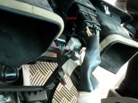
3rd Gen Dash Clock Fix

Ha! I completely understand, Durk. I've been using my HU clock for the past year. While it's OK, it's still not as convenient as the dash clock. Plus, it always bothered me that it was there...but didn't work. Now I can sleep at night. :-)
 
the pins are not in the clock like the one shown they simply slide in and the springs make contact

That's how my 99 is. I bet the circuit boards are very similar. You just need to remove the springs and "hard-wire" those 4 connections.
 
LOL! Yep, it's a total pain to keep them in line. Try my method (trim the pins and just use solder on both contact points), that is if there is anything left of your clock!
 
the pins are not in the clock like the one shown they simply slide in and the springs make contact

Elton, I think the OP's were like yours BEFORE his mod. If I understand correctly, he took the pins out, threw away the springs, and then soldered the pins to the board upside down so that they then protrude through the case. It's been a few years since I effed with mine, but that's what I understand.
 
I am so confused now....I just went and tore the dash apart to get to my clock and found that there is NO wires going to the back of my clock at all. There is a 4 pin receptical on the back of the clock...but the freakin' wires aren't there to plug into it!

I don't remember ever tucking them away during my stereo install. Are they bundled up with tape along with the other wires going to that center piece of dash trim (the power back window switch, hazard button and a couple others...defrost maybe, I don't remember now)? There is white tape around that bundle of wires, and it doesn't look like they have ever been untaped.

Weird....
 
I am so confused now....I just went and tore the dash apart to get to my clock and found that there is NO wires going to the back of my clock at all. There is a 4 pin receptical on the back of the clock...but the freakin' wires aren't there to plug into it!

I don't remember ever tucking them away during my stereo install. Are they bundled up with tape along with the other wires going to that center piece of dash trim (the power back window switch, hazard button and a couple others...defrost maybe, I don't remember now)? There is white tape around that bundle of wires, and it doesn't look like they have ever been untaped.

Weird....

I looked at mine this week and had the same problem, the wire was plugged into the dead spot behind the rear window switch. But when I plugged the clock in it still did not work.
 

Attachments

  • WIRING.jpg
    WIRING.jpg
    123 KB · Views: 4,279
This thing is killing me! I have been screwing with it for the past two hours. I have soldiered on the little posts and I have inspected it for way to much time and I just can't figure it out. It will light up when I smash the screen down into the board as hard as I can, and it will stay lite for a few seconds...then it turns off. Then I take a little screw driver and gently pry the screen up off the board and it turns back on....for a few seconds. Then I smash it again, and back and forth we go.

There are VERY few diodes or whatever they are on the board. The majority of them are actually under the screen so I can't get at them to inspect very good or soldier, but I can get my screw driver on them and they don't budge. I convinced it is actually something loose inside the screen and I can't get at that because it's sealed in glass.

What a disappointment...and a frusteration!
 
Mine is a 98 and if not the same, it's very similar. I don't have mine out right now and I don't remember exactly what it looks like.

It does have the 4 pins and spring contacts.

Mine was dead while in dash and worked great when I'd take it out to see what was up.

I finally just took it into my bench and soldered all the connections!

Been working great for about 2 months now!
 
Sorry for late replies. I'm out of town and have been stuck working night shift lately. :sleepy: (Notification e-mails still aren't working for me either)

Dude, thank you! It worked for me. I ended up with a slightly different approach, but the same result. I couldn't keep the pins aligned, so the solder would break upon reassembly. I ended up clipping off the small ends of the pins, pushing them back into the plastic housing, then putting a small dab of solder on each pin end. I then filled in the corresponding circuit board "holes" with solder. upon reassembly, the cut pin ends and the new solder "bumps" came into contact, and are held in contact by the two small screws holding the board to the plastic housing.

Works great!

Thanks again.
Ya, it is kind of a pain to get the pins lined up properly. I barely soldered them initially (so I could still move them w/o too much force), lined them up and checked fit, then soldered them the rest of the way. Just be careful not to pull the copper traces off of the circuit board!


the pins are not in the clock like the one shown they simply slide in and the springs make contact
Read my post a little more carefully. As has already been mentioned, the pins in mine were also mounted in the back case. They slide out from the outside in with a little bit of pushing. The springs are intended to make contact, which is the weak link in the system.


Dirt4dinner and jdmidwest - I noted the dead clock harness port in my write-up. Past clock threads have mentioned it as well. Don't feel bad; there have been more than a few ppl who've found that theirs was plugged into the wrong spot!


This thing is killing me! I have been screwing with it for the past two hours. I have soldiered on the little posts and I have inspected it for way to much time and I just can't figure it out. It will light up when I smash the screen down into the board as hard as I can, and it will stay lite for a few seconds...then it turns off. Then I take a little screw driver and gently pry the screen up off the board and it turns back on....for a few seconds. Then I smash it again, and back and forth we go.

There are VERY few diodes or whatever they are on the board. The majority of them are actually under the screen so I can't get at them to inspect very good or soldier, but I can get my screw driver on them and they don't budge. I convinced it is actually something loose inside the screen and I can't get at that because it's sealed in glass.

What a disappointment...and a frusteration!
Have you tried re-flowing the solder on all of the connection pins for the clock screen? Just be sure not to get it too hot, just enough to melt the solder. Be especially careful if you re-flow the small smt components, as too much heat will kill those!
 
Thanks alot for the write up! I took the clock apart and looked at it but everything looked like it was in good shape. For some reason though when I plugged it back in it all WORKS now! I wonder what it was. I'm glad I got this to work, it's been bugging me for a while!
 
Thanks for posting. I had to replace my HVAC lights and the pictures/directions to remove the console helped confirm that there were no screws.
 
No problem, glad I could help!

Getting the four pins lined up is the trickiest part of this fix. That's why initially I barely soldered them on so I could still work them into place, then carefully lined them up and added more solder for the permanent joint.

I think the weird burned-looking spot you noticed on the screen may be where they purge/fill the glass envelope with inert gas (or maybe neon) and then seal it off during manufacturing.
 
Well, I'll be darned. This looked simple enuf, so I went to take a look and it worked just as you said.........popped the panel off, looked behind it.....and no wiring harness or plug to the clock. Looked all over with a flashlight, even pulled the radio out, nothing. I'm amazed and baffled. No cut off wires, nothing folded back out of the way.......... I dunno.

Lar.
 
Well, I'll be darned. This looked simple enuf, so I went to take a look and it worked just as you said.........popped the panel off, looked behind it.....and no wiring harness or plug to the clock. Looked all over with a flashlight, even pulled the radio out, nothing. I'm amazed and baffled. No cut off wires, nothing folded back out of the way.......... I dunno.

Lar.

Your are the umpteenth victim of the dummy plug. Your clock harness is plugged in to a blank hole in the center fascia--I think its lower and to the left of the clock. This does not mean it plugging it in will fix the clock, because this often happens when someone is trying to fix an already broken clock--but it might.
 

Members online

Forum statistics

Threads
278,306
Messages
3,554,045
Members
248,016
Latest member
Advally Service

Trending content

Back
Top