

CO_FlyFisher
New member
As you all know, the dashboard clocks on our 3rd gen 4Runners tend to die early. Mine starting showing the symptoms last winter, and it recently completely bought the farm. My wife has been hounding me to fix it saying that she uses it more than she ever realized before it broke. I’ve seen all the clock threads here over the years, and there are now a couple people offering services fixing these clocks for a (not so small) fee. I think I’m pretty mechanically and electronically inclined, so I figured if they were able to fix them, I probably could too.
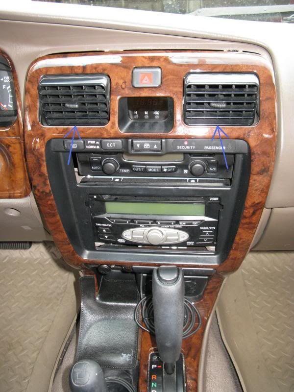
The quest begins with pulling the center console trim piece off. This really isn’t hard, especially when you only need to get to the clock. Personally, I find it easiest to push the heater vents in at the bottom which allows me to easily grab and pull on the strip of trim directly below the vents (see blue arrows).
Carefully pull the piece straight off, then kind of pivot it toward you like it is hinged at the bottom (it isn’t, but it IS connected to the lower trim piece in a way). Once it comes free of the clips holding it on – there are no screws – it will hold itself in place because of the wiring harnesses still attached to the backside (see red arrows for clips, fuschia arrows for their slots).
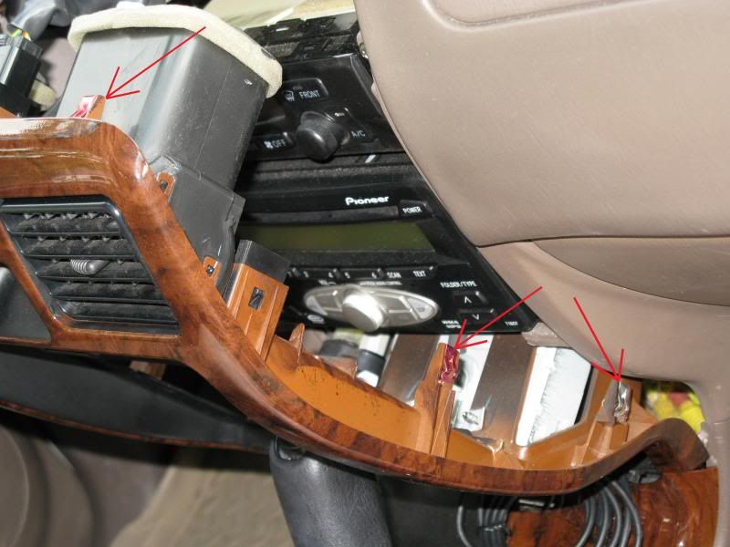
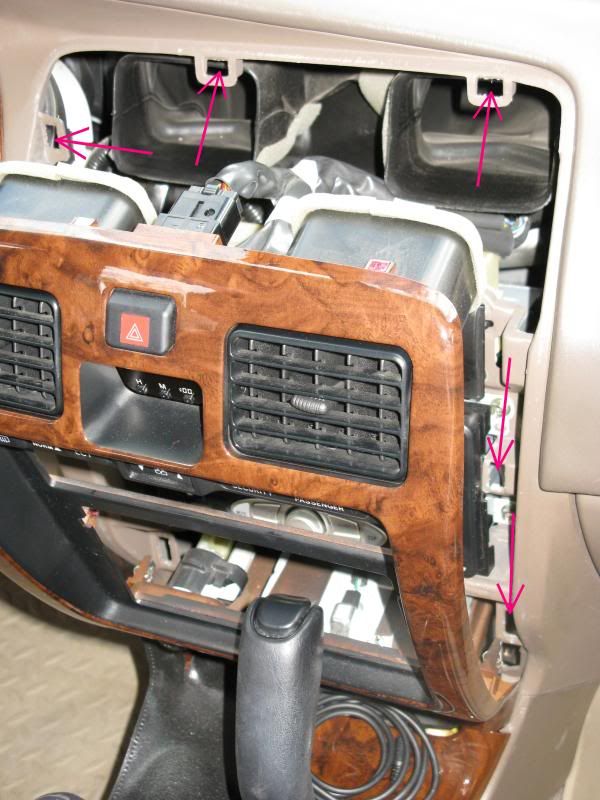
I found it easiest to remove the wiring harness from the hazard light switch above the clock in order to gain better access to the clock. I actually wound up reconnected the clock harness to give me something to hang onto.
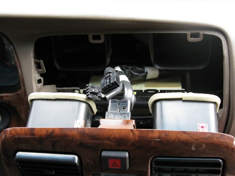
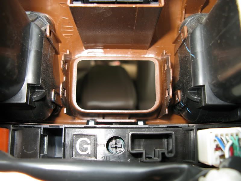
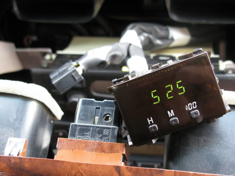
With a small, wide-bladed object (screwdriver, butter knife, etc.) carefully pry up on the center “wing” of the trim on the driver’s side of the clock (right side in the picture), freeing the two tabs holding it in. Lightly press on the clock face from the front and it should easily pivot out of the holder in the trim. Doing it this way will prevent you from having to pry up on the two tabs on the opposite side individually, which risks breaking them (I split one in half, but it still does its job OK). Note the dummy slot for the clock wiring harness at the bottom right in the picture. Nobody seems to know why it’s there…
Once you have the clock module out of the trim panel, carefully remove the wiring harness and take the clock to your workbench. Start by removing the face of the clock. To do this, put the clock face-down, and carefully pry up and free the two black plastic tabs on either the top or bottom. This will free the face from the module. Set it aside, being careful not to let the three buttons fall out. Turn the clock over and you will see two small Philip’s-head screws on the left side; one on top and one on the bottom. Remove these screws and set them aside. This will free the circuit board of the clock from its housing. Lift it out and set it aside for now.
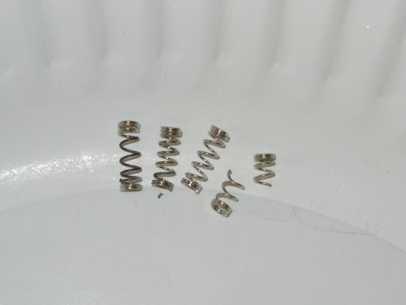
You should now see the four silver electrical connection pins for the clock on the left side of the housing. Each one has a small silver spring around it. These springs are what are supposed to make contact between the pins and the back of the circuit board. Honestly, I think it is a poor design. These springs are the cause of ALL your problems. Well, maybe not, but they ARE responsible for the clock not working in most cases. They appear to be silver-coated (I suppose it could be chrome, but the color looks like real silver to me, which is a very good electrical conductor), but in my case, the coating was flaking off. I think this has lead to loss of electrical conductivity, thus the flaky clock. Also, while I was inspecting the springs, one of them broke in half without hardly any effort. I think it boils down to the fact that these springs have simply corroded and failed.
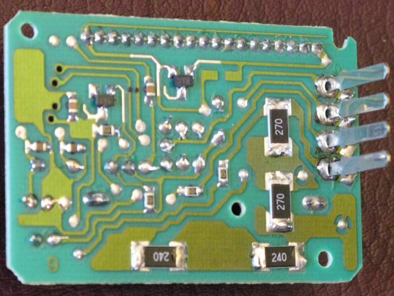
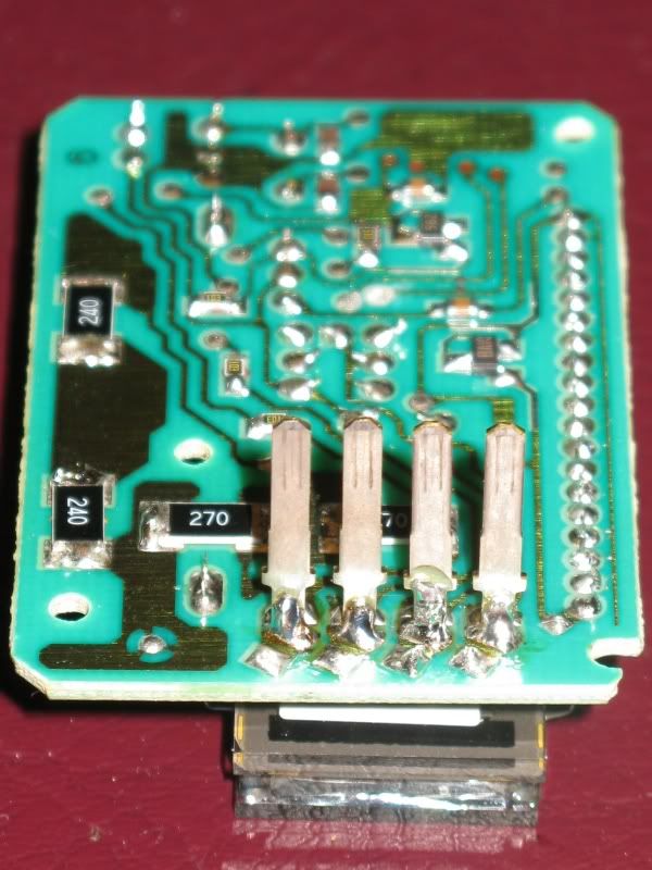
I considered seeking replacements for the springs and refurbishing the clock the same way it was built from the factory. However, upon closer inspection and a little thought, I decided a more robust solution would be to solder the pins directly to the circuit board. I’m thinking that the reason this wasn’t done from the factory was simply for ease of production (I could be wrong). The four pins push through the case back pretty easily (from outside inward), so it’s just a matter of getting them soldered onto the board perpendicularly, laying roughly in the same plane, and spaced properly. I lightly soldered each one on, then lined them up and added solder to get a good, solid joint on one side. Be careful not to overdo the solder joint or the pins won’t fit back into their slots in the case. You must keep the solder pretty close to the board and don’t let it go too far down the pin. Here are a few pictures of the pins soldered to the main board before reassembly of the clock.
edit: While I was in there, I also re-flowed the solder joints on all of the components. The solder joints on the large resistors (marked 240 and 270) are known to crack occasionally. This wasn't the problem with mine, but it could be with yours.
Long story short, this repair worked fine for me. My clock is back working 100%, and it didn’t cost me $30 - $40 to send it somewhere and wait for someone else to do the work. I’m not knocking these guys that offer their services to fix them as not everyone will be able to do this repair work themselves, but IMHO they do charge a bit too much for this job.
Anyway, hope this helps someone out!

The quest begins with pulling the center console trim piece off. This really isn’t hard, especially when you only need to get to the clock. Personally, I find it easiest to push the heater vents in at the bottom which allows me to easily grab and pull on the strip of trim directly below the vents (see blue arrows).
Carefully pull the piece straight off, then kind of pivot it toward you like it is hinged at the bottom (it isn’t, but it IS connected to the lower trim piece in a way). Once it comes free of the clips holding it on – there are no screws – it will hold itself in place because of the wiring harnesses still attached to the backside (see red arrows for clips, fuschia arrows for their slots).
I found it easiest to remove the wiring harness from the hazard light switch above the clock in order to gain better access to the clock. I actually wound up reconnected the clock harness to give me something to hang onto.
With a small, wide-bladed object (screwdriver, butter knife, etc.) carefully pry up on the center “wing” of the trim on the driver’s side of the clock (right side in the picture), freeing the two tabs holding it in. Lightly press on the clock face from the front and it should easily pivot out of the holder in the trim. Doing it this way will prevent you from having to pry up on the two tabs on the opposite side individually, which risks breaking them (I split one in half, but it still does its job OK). Note the dummy slot for the clock wiring harness at the bottom right in the picture. Nobody seems to know why it’s there…
Once you have the clock module out of the trim panel, carefully remove the wiring harness and take the clock to your workbench. Start by removing the face of the clock. To do this, put the clock face-down, and carefully pry up and free the two black plastic tabs on either the top or bottom. This will free the face from the module. Set it aside, being careful not to let the three buttons fall out. Turn the clock over and you will see two small Philip’s-head screws on the left side; one on top and one on the bottom. Remove these screws and set them aside. This will free the circuit board of the clock from its housing. Lift it out and set it aside for now.
You should now see the four silver electrical connection pins for the clock on the left side of the housing. Each one has a small silver spring around it. These springs are what are supposed to make contact between the pins and the back of the circuit board. Honestly, I think it is a poor design. These springs are the cause of ALL your problems.
Well, maybe not, but they ARE responsible for the clock not working in most cases. They appear to be silver-coated (I suppose it could be chrome, but the color looks like real silver to me, which is a very good electrical conductor), but in my case, the coating was flaking off. I think this has lead to loss of electrical conductivity, thus the flaky clock. Also, while I was inspecting the springs, one of them broke in half without hardly any effort. I think it boils down to the fact that these springs have simply corroded and failed.
I considered seeking replacements for the springs and refurbishing the clock the same way it was built from the factory. However, upon closer inspection and a little thought, I decided a more robust solution would be to solder the pins directly to the circuit board. I’m thinking that the reason this wasn’t done from the factory was simply for ease of production (I could be wrong). The four pins push through the case back pretty easily (from outside inward), so it’s just a matter of getting them soldered onto the board perpendicularly, laying roughly in the same plane, and spaced properly. I lightly soldered each one on, then lined them up and added solder to get a good, solid joint on one side. Be careful not to overdo the solder joint or the pins won’t fit back into their slots in the case. You must keep the solder pretty close to the board and don’t let it go too far down the pin. Here are a few pictures of the pins soldered to the main board before reassembly of the clock.
edit: While I was in there, I also re-flowed the solder joints on all of the components. The solder joints on the large resistors (marked 240 and 270) are known to crack occasionally. This wasn't the problem with mine, but it could be with yours.
Long story short, this repair worked fine for me. My clock is back working 100%, and it didn’t cost me $30 - $40 to send it somewhere and wait for someone else to do the work. I’m not knocking these guys that offer their services to fix them as not everyone will be able to do this repair work themselves, but IMHO they do charge a bit too much for this job.
Anyway, hope this helps someone out!
Last edited:


 Mine still works, but about every 2-3 days, it's kinda of dim. I can tell it's dying...just a matter of time.


