Advice requested from those of you who have mounted tires & balanced wheels at home

Status
Not open for further replies.
I will likely have the vehicle to work on the other four wheels on the weekend so I want to order the right type of wheel weights, in the right sizes.

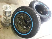
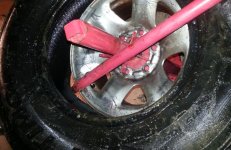
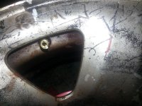
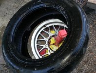
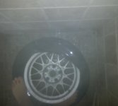
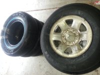
  1. Below is a picture of the front of the rim on the balancer
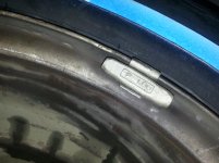
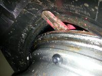
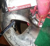
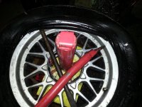
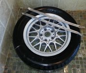
  2. And below that is a picture of the rear of the steel rim
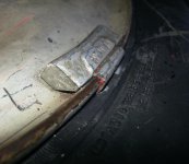
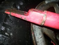
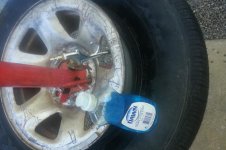
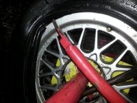
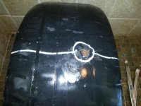
  3. Below that is a picture of the old existing weight

From that little bit of information (which is all I have), do you know enough about balancing to know which TYPE of weights to purchase?

For the actual process, I have been researching the steps by watching all the youtube videos on how to use the HF bubble balancer, where it seems the process of determining where and how much weight seems to be as easy as using a traditional (offset) balance scale.

1. Use the head of the HF wheel balancer to find a flat spot
2. Put the head on the post and zero the inner bubble with 3 screws
3. Remove all weights and debris from the tire/wheel assembly
4. Place the tire/wheel assembly on the HF bubble balancer
5. Determine balance weight by placing weights to level the bubble
6. Mark the weight and position of the weight on the tire or wheel
7. Divide the weight amount in half for each position on the wheel
8. Clip half the weight on both sides of the rim at the desired position
9. Put the best balanced wheels on front, and the worst as the spare
10. Test drive up to 80mph (if possible) & dynamic balance if it vibrates

My main question at the moment is which kinds of weights to buy?
Googling, it seems "Perfect Equipment" sells a lot of the weight out there.

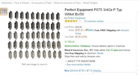
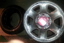
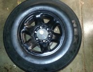
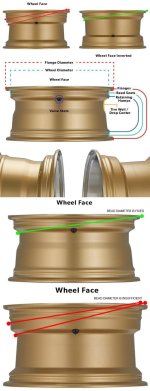
For example, here is a $17 50-piece set on Amazon: 3/4OZ P TYP WHLWT BX/50
But they're all 3/4 ounce, and I probably need fewer weight with better variety.

O'Reilly seems to sell Perfect Equipment weights:

But you have to know what you need as there are multiple types, some of which say "Not Legal For Sale In California, Illinois, Maine, New York, Washington and Vermont" where I am.

Since lead is not an option, there are only "steel" or "zinc".
Which would you use? Why?

The choices in "types" seem to be:
1. AW Series, Steel or Zinc, Coated
2. FN Series, 5g Steel or Zinc, Coated
3. IAW Series, 5g Steel or Zinc, Coated
4. MCS Series, Steel or Zinc, Coated
5. TZ Series, 0.25 Oz. Steel or Zinc, Coated

From that little bit of information (which is all I have), do you know enough about balancing to know which TYPE of weights to purchase (and what variety)?
 

Attachments
  • 1_balance_wheel.jpg
    1_balance_wheel.jpg
    57.1 KB · Views: 742
  • 2_balance_tires.jpg
    2_balance_tires.jpg
    64.9 KB · Views: 2,276
  • 3_old_weight.jpg
    3_old_weight.jpg
    62.2 KB · Views: 742
  • 4_perfect_equipment_weight_set.jpg
    4_perfect_equipment_weight_set.jpg
    51.7 KB · Views: 1,188
Last edited:
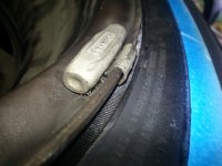
If it helps you to tell me the type of weights to buy (and sizes), here is a closeup of both the one (old) weight on the front of the rim and the one (old) weight on the rear of the rim.

What type of weight would you get for these rims, and what sizes?
  1. AW Series, Steel or Zinc, Coated
  2. FN Series, 5g Steel or Zinc, Coated
  3. IAW Series, 5g Steel or Zinc, Coated
  4. MCS Series, Steel or Zinc, Coated
  5. TZ Series, 0.25 Oz. Steel or Zinc, Coated
 

Attachments

  • 5_weight_on_front.jpg
    5_weight_on_front.jpg
    54.7 KB · Views: 727
  • 6_weight_on_rear.jpg
    6_weight_on_rear.jpg
    50.6 KB · Views: 1,882
Last edited:
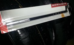
For the record, I also picked up the tire valve changing tool, just so that I could see how it differs from the method that I used on the first tire.

I'll let you know how it works out compared to the 4-way crossbar tool so that the next person knows better which to bother with (since you really don't need either to remove or replace valves).

O'Reilly 15-3606 UPC: 639601536061
 

Attachments

  • 7_tire_valve_installation_tool.jpg
    7_tire_valve_installation_tool.jpg
    42 KB · Views: 727
So that everyone can benefit from the effort, here is a quick summary of the score of lessons learned for the tire weight question:

QUESTION: *What style weight does the wheel take?*
1. For the steel wheels I am working on, they take a "P" type weight.
2. That P type weight is sold in lead, steel, and zinc, coated and uncoated in a variety of weights generally from 1/4 ounce to 2 ounces each.
3. Since I'm in California, lead isn't an option.
4. Zinc or steel, doesn't really matter (it seems).
5. Coated or uncoated, for such old steel wheels anyway, doesn't really matter either (it seems).
6. The way the tire shops figure out the style is the have a template that they hold against the rim as there are about a dozen different clamp on styles of wheel weights for passenger cars.
7. In a pinch, I can use the stick-on weights instead of clamp-on weights.
8. Any tool will work for the clamp on weight but it's best to have a special pair of pliers which installs, removes, and trims the weights.
9. Each weight is designed for a specific shape rim, so, putting the wrong style of weight on can easily result in losing the weight over time during driving.
10. Lots of shops put on the wrong weights so caveat emptor (you have to know enough to recognize the right and wrong weights for your wheels).

In the SUV I'm working on, the spare tire is a *different* steel wheel than the other four wheel, so I'll have to check it to see if it uses the same P style weight (but it probably does).
230898d1481846655-advice-requested-those-you-who-have-mounted-tires-balanced-wheels-home-a_rim_gauge.jpg

The main question of WHERE do you get the weights, the answer is even simpler.

QUESTION: Where do you buy weights for balancing wheels at home?
1. You buy them on the web in boxes of about 50 or in an assortment.
2. You will NOT likely find them at consumer auto parts stores.
3. The stores (O'Reillys, Pep Boys, Autozone) can *order* them.
4. But they don't have any in stock where I live
5. Although Harbor Freight has 1/2 and 1 ounce sticky weights in stock
6. And industrial supply houses will also stock the weights
7. You probably need sizes from 1/4 ounce to 2 ounces in 1/4-ounce increments.
8. You probably want to have on hand at least 2 to 4 weights of each size per wheel (on average) because you often split weight putting half on each side of the rim.
9. Weights are often sold in boxes of 50 so, like bandaids, your best bet is buying them one size at a time and making your own assortment kits.
10. Some people collect used weights by visiting the parking lot of the tire shops at midnight, to pick up the myriad stray weights lying around.
230914d1481856201-advice-requested-those-you-who-have-mounted-tires-balanced-wheels-home-wheel_weight_sample.jpg

I hope these answers help others, as the score of answers above are all basic answers to the original question, which I didn't know at the time I posed the question a day or two ago.
 
I used to work in a fish store when I was in high school on a work permit, and I learned a LOT about the fibs fish stores tell their customers (e.g., we would slice haddock in half and sell the thick half as scrod and the thin half as cod at two different prices).

So the great thing about knowing something is that you can tell when someone else is telling a fib.

To that end, I only have a single Toyota wheel in my possession, which has two very different looking wheel weights on them, and, from the looks of them, they could even be of two different ages (although it could just be that the front weight looks older because of the additional curb wear and tear).

However, if the weights were put on (or left on) by the last installer, then they seem to be improperly mounted.

Does it make a difference?
Probably not.

But my point is that knowing how to do something allows you to tell if someone else is doing that job correctly.

Apparently the weight on the right in the photo below (which was on the inside of the rim) is the wrong type, so, we know this wheel wasn't balanced by the book (which fits my assessment that almost no tire is ever mounted and balanced correctly when taken to a tire shop).
230927d1481860698-advice-requested-those-you-who-have-mounted-tires-balanced-wheels-home-side_by_side_weight.jpg
 
I've done now two passenger tires for a sedan, and both were a breeze.

But breaking the bead on these Optimos is not something you want to do in front of polite company, as your vocabulary will not be genteel during the process.

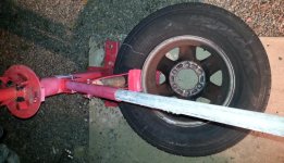
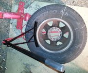
To get back to the mounting and balancing so that others can benefit who want to do their own mounting and balancing at home, I mounted and balanced another wheel last night where I continued to learn that the Harbor Freight equipment is stressed to its max by these Optimo tires, even with the block of wood shoring up the breaker arm, and a longer pipe for leverage:
(see photo below)

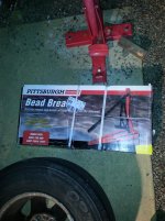
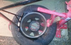
The wood fell out and the metal starting bending again, so I broke out the HF Pittsburgh Bead Breaker item# 92961
(see photo below)

Here you see the old and new bead breakers for size comparison:
(see photo below)

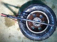
Just in case it was possible, I tried both at once, but you need two people if it's gonna stand a chance of working.
(see photo below)

Even with the newer bead breaker, it's still very difficult to break these Optimo beads:
(see photo below)

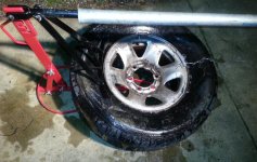
Finally, I was able to get the back bead broken (which is reputedly the hardest one):
(see photo below)

I worked my way around the edges, to ensure the entire inside bead was loose:
(see photo below)

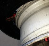
Flipping the 15-inch tire to the front side, a design flaw in the bead breaker showed up which was that the rim is a different diameter which doesn't touch the front of the bead breaker (under the tire) which causes the bead breaker to lift up, making it useless.
(see photo below)

The HF bead breaker needs to be an inch or three longer, so I grabbed whatever was handy to extend the length of the tapered end:
(see photo below)
 

Attachments

  • 0_long_arm_on_bead_breaker.jpg
    0_long_arm_on_bead_breaker.jpg
    66.8 KB · Views: 825
  • 1_break_out_the_bead_breaker.jpg
    1_break_out_the_bead_breaker.jpg
    134.2 KB · Views: 851
  • 2_compare_bead_sizes.jpg
    2_compare_bead_sizes.jpg
    91.7 KB · Views: 697
  • 3_try_both_at_once.jpg
    3_try_both_at_once.jpg
    59.4 KB · Views: 590
  • 4_it_is_very_hard.jpg
    4_it_is_very_hard.jpg
    51.6 KB · Views: 644
  • 5_it_is_very_hard.jpg
    5_it_is_very_hard.jpg
    89.9 KB · Views: 652
  • 6_the_front_lifts_up.jpg
    6_the_front_lifts_up.jpg
    73.5 KB · Views: 678
  • 8_need_to_hold_the_front_down.jpg
    8_need_to_hold_the_front_down.jpg
    73.9 KB · Views: 544
Last edited:
It took me a couple of tries to realize that the extension needs to only be on the tapered end because you need the little welded-in chock that holds the wheel close to the vertical stem of the bead breaker.
(see photo below)

So I moved the extension out to just cover the last few inches of the tip of the tool base:
(see photo below)

Once the top bead was broken (which is far easier than the bottom bead once you nail down the bead-breaking tool), I easily removed the top bead from the wheel on the tire changer tool.
(see photo below)

For reference, for someone doing this in the future, the tool goes with the step-side up, like this:
(see photo below)

The tool goes in the same orientation to remove the bottom bead from the rim, which is only very slightly more difficult than removing the top bead from the rim.
(see photo below)

Here is a closeup of the bottom bead coming off and the positioning of the tool tip:
(see photo below)

This removes the tire from the wheel:
(see photo below)

For the record, I destroyed the tire valve in the process, so, it's a good thing to do the tire valve last before you put the tires back on the rim.
(see photo below)
 

Attachments

  • 9_but_you_need_the_bump.jpg
    9_but_you_need_the_bump.jpg
    65.4 KB · Views: 569
  • 10_needs_only_on_the_end.jpg
    10_needs_only_on_the_end.jpg
    83.3 KB · Views: 623
  • 11_top_bead_is_easy.jpg
    11_top_bead_is_easy.jpg
    84.4 KB · Views: 609
  • 12_put_the_step_side_up.jpg
    12_put_the_step_side_up.jpg
    75.6 KB · Views: 574
  • 13_same_with_the_bottom_bead.jpg
    13_same_with_the_bottom_bead.jpg
    78 KB · Views: 1,229
  • 14_bottom_bead_position.jpg
    14_bottom_bead_position.jpg
    75.6 KB · Views: 570
  • 15_tire_off_wheel.jpg
    15_tire_off_wheel.jpg
    60.6 KB · Views: 576
  • 16_damaged_valve_threads.jpg
    16_damaged_valve_threads.jpg
    74.6 KB · Views: 594
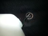
I didn't get to use the fancy valve-removal-and-replacement lever because the threads were so messed up, so I just cut off the valve, and I used the fancy lever tool to insert the valve, but, it really wasn't worth the trouble since it would have been easier to just pull the tube on with the end of one of my threaded compressor soccer-ball filling attachments.
 

Attachments

  • 17_replaced_valve_stem.jpg
    17_replaced_valve_stem.jpg
    109.7 KB · Views: 641
Chipping off the old weights was easy with a hammer and blunt chisel:
231401d1482187331-advice-requested-those-you-who-have-mounted-tires-balanced-wheels-home-000_removing_the_old_weight.jpg


This tire was a little cranky when filling with air as I had a tougher time cajoling the bead into position to seal. I needed three hands, two to hold the tire against the rim and one to press the trigger on the fast fill (the Schrader valve was removed) for the air.

Because the rim was so scratched up, I decided, on a whim, to spray paint it black. Dunno how that will look (nor if the owner will even notice) but it's done already. :)

Here is the wheel on the static balanceer...
 

Attachments

  • 001_filling_the_tire_with_air.jpg
    001_filling_the_tire_with_air.jpg
    54.6 KB · Views: 601
  • 002_balance_is_goog.jpg
    002_balance_is_goog.jpg
    78.9 KB · Views: 671
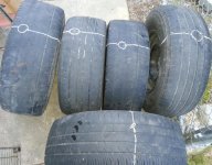
For practice, I decided to mount and dismount and repair these five tires today, two of which are 55-series alloy wheel tires and the rest are 75-series SUV tires (all of which are holed within an inch of the shoulder):
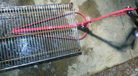
(see photo 1 below)

Ignoring the treadwear, what do you think of the safety and efficacy of my patch technique?

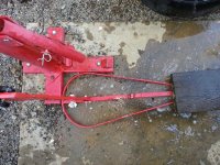
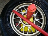
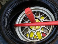
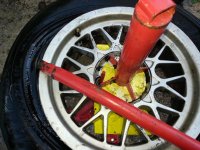
The first thing I did was set up the bead breaker with the wood on the sharp end and I butted the round end against the tire changing machine:
(see photo 2 below)

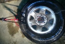
Then I easily broke the bottom bead on the 55-series alloy wheel tires:
(see photo 3 below)

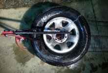
Flipping the wheel, it was even easier to break the top bead of the lower-profile tire:
(see photo 4 below)

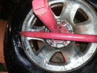
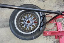
Once the beads were broken, I put the wheel outward side up on the tire changer to remove the top bead:
(see photo 5 below)

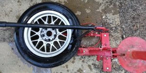
The top bead came off with a simple 360 degree rotation of the tire iron:
(see photo 6 below)

The bottom bead requires the breaker bar to be inserted the same way:
(see photo 7 below)

Then the bottom bead came off the rim almost as easily as did the top bead:
(see photo 8 below)
 

Attachments

  • 000_holes_in_tires.jpg
    000_holes_in_tires.jpg
    76.2 KB · Views: 1,330
  • 00_bead_breaker_board.jpg
    00_bead_breaker_board.jpg
    106 KB · Views: 1,370
  • 02_breaking_bottom_bead.jpg
    02_breaking_bottom_bead.jpg
    74 KB · Views: 1,810
  • 03_breaking_top_bead.jpg
    03_breaking_top_bead.jpg
    151.1 KB · Views: 1,588
  • 05_done_with_top_bead.jpg
    05_done_with_top_bead.jpg
    83.8 KB · Views: 1,297
  • 06_removing_bottom_bead.jpg
    06_removing_bottom_bead.jpg
    119.4 KB · Views: 1,256
  • 07_removing_bottom_bead.jpg
    07_removing_bottom_bead.jpg
    85.6 KB · Views: 1,350
  • 04_removing_top_bead.jpg
    04_removing_top_bead.jpg
    81.9 KB · Views: 1,380
Now I had the wheel off the alloy rim, I could look inside to inspect for internal damage:
(see photo 1 below)

After patching the tire first with a plug, and then with a patch, I slid the bottom bead onto the rim without any problem whatsoever.

For one of the alloy-wheel 55-series tires, the top was only slightly hard, but for the second tire of the matched set, I still haven't been able to get the tire on the rim!
(see photo 2 below)

In fact, it took so much force for the second tire of that set, that it bent the tip of the tire iron!
(see photo 3 below)
 

Attachments

  • 08_tire_off_rim.jpg
    08_tire_off_rim.jpg
    89.7 KB · Views: 1,511
  • bent_tire_iron.jpg
    bent_tire_iron.jpg
    68.7 KB · Views: 1,329
  • bent_tire_iron_tip.jpg
    bent_tire_iron_tip.jpg
    65.6 KB · Views: 1,248
The trick on the stubborn tire above will be, I'm told, to knee down the top bead so that it is in the drop center.

I'm told that the bottom bead isn't the problem so my attempts to lift the bottom bead into the drop center were to no avail.

I will report back on how this works to drop the top bead into the drop center, as that is more easily said than actually done.

REPORT BACK:
After leaving the recalcitrant tire and wheel assembly outside in the cold in the 3/4-mounted position for about a week, I finally gathered up the courage to tackle the job again, despite it having taken me a couple of hours and bent the strongest of steel implements, and damaged both the rim and the bead of the experimental tire, I followed the words of advice to ensure that the top bead was in the drop center.

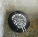
I don't know if heating the entire assembly in the shower helped or not (I didn't even use detergent), but it just popped right into place when I stepped on the bead to ensure it was in the drop center for as much of the circumferential arc that I could get it.

Much to my relief, the tire bead popped into place with just the use of the two 24-inch tire irons, where there was no need for much force and no need for pliers or a helper, or anything.
So, while most tires will go into place whether or not you lower the top bead into the drop center, some will NEVER go on the rim unless you do so.
Lesson learned!

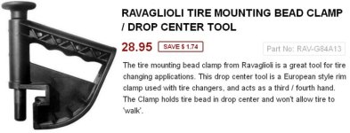
NOTE: In the future I might consider this "bead tool" which holds the tire in the drop center.
 

Attachments

  • bead_seating.jpg
    bead_seating.jpg
    41.2 KB · Views: 1,282
  • 01_bead_shower.jpg
    01_bead_shower.jpg
    65.7 KB · Views: 1,231
  • 02_bead_shower.jpg
    02_bead_shower.jpg
    23.2 KB · Views: 1,206
  • 03_bead_shower.jpg
    03_bead_shower.jpg
    81.1 KB · Views: 1,353
  • 04_bead_shower.jpg
    04_bead_shower.jpg
    55.2 KB · Views: 1,258
  • Clipboard.jpg
    Clipboard.jpg
    123.8 KB · Views: 6,469
  • beadtool.jpg
    beadtool.jpg
    124 KB · Views: 332
Last edited:
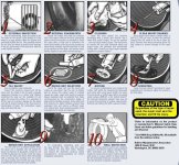
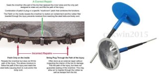
Meanwhile, I practiced repairing tires with two-piece plugs and patches using the REMA suggested method.
(see pdf below)

One trick I learned was to place two tires flat on the ground and then the tire that I'm working on upright in the hole of the top of the two tires.
That gave me a "workbench" of about the right height to work on while I was on my knees.
I guess if I had enough tires, I could pile them up higher and do the job standing, but I didn't think of that until I wrote this just now.

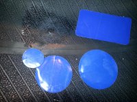
I wasn't sure which patch to use because I had a variety in my patch kit, so I tried a larger and smaller patch on various tires.
(see photo 1 below)

When I tried the smaller patch, I found it became bumpy because I probably didn't buff the inner plug flush enough.
(see photo 2 below)

I found the larger patch seemed to feel better, and is what I'd use in the future.
(see photo 3 below)
 

Attachments

  • Basic_Steps_of_Tire_Repair.jpg
    Basic_Steps_of_Tire_Repair.jpg
    138.5 KB · Views: 1,532
  • Basic_Steps_of_Tire_Repair.pdf
    Basic_Steps_of_Tire_Repair.pdf
    518 KB · Views: 166
  • b01_patch_sizes.jpg
    b01_patch_sizes.jpg
    100.2 KB · Views: 1,161
  • b02_small_patch.jpg
    b02_small_patch.jpg
    47.2 KB · Views: 1,150
  • b03_larger_patch.jpg
    b03_larger_patch.jpg
    86.3 KB · Views: 1,146
  • b00_remove_nail.jpg
    b00_remove_nail.jpg
    80.2 KB · Views: 1,160
  • b00a_dremel_plug.jpg
    b00a_dremel_plug.jpg
    137.1 KB · Views: 331
  • one_piece_patch_plug.jpg
    one_piece_patch_plug.jpg
    45.1 KB · Views: 1,196
Last edited:
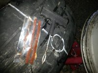
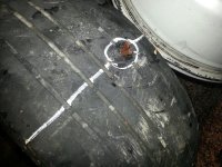
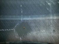
I post my first patch-and-plug repair so that others may benefit and critique the method, so that we all learn.

The first step was to remove the bolt, which apparently was blunt on both ends, so I must assume it simply stuck in the tread, and over the years, worked its way into the tire, finally puncturing the tire in the inexorable process.
(see photo 1 below)

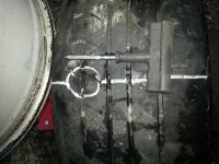
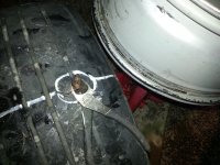
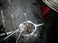
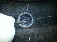
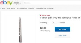
The next step was to ream the hole with a carbide bit, I guess to blunt the torn steel belts and to ensure a uniform hole of about 1/16th to 1/8th inch smaller than the plugs, which are generally 1/4 inch sized (I think).
(see photo 2 below)

The sell carbide bits which are to be operated in a drill at lower than 1,200 RPM, but I didn't have one so I used the hand tool, at the same time I probed the angle of the penetration, which was pretty much at 90 degrees.
(see photo 3 below)

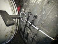
I grabbed a string patch, which seems to be nylon yard with rubber glooped and a plug insertion tool, which when lubricated with vulcanizing cement, and then inserted, twisted, and pulled out, easily inserted the plug.
(see photo 4 below)

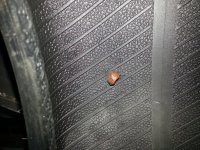
Here is what the plug looked like from the outside of the tire, which is the way it would stay if this were a side-of-the-road emergency repair.
(see photo 5 below)

The plug stuck out on the inside about the same distance as it stuck out on the outside, but neater because it was the loop end in the middle.
(see photo 6 below)

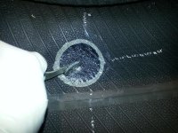
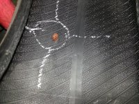
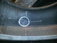
I circled the area to be buffed by using a grease pen, and put lines so that I could find the location once the area is buffed and covered with cement:
(see photo 7 below)

To make the outside neater, I tried to cut the protruding ends with a pair of diagonal cutters, but they were useless against the floppy rubber.
(see photo 8 below)
 

Attachments

  • a01_remove_object.jpg
    a01_remove_object.jpg
    80.2 KB · Views: 311
  • a02_ream_hole.jpg
    a02_ream_hole.jpg
    73.5 KB · Views: 1,194
  • a03_aim_reamer.jpg
    a03_aim_reamer.jpg
    68.6 KB · Views: 1,161
  • a04_prepare_plugs.jpg
    a04_prepare_plugs.jpg
    77 KB · Views: 1,110
  • a05_plug_protruding_outside.jpg
    a05_plug_protruding_outside.jpg
    75 KB · Views: 1,151
  • a06_plug_protruding_inside.jpg
    a06_plug_protruding_inside.jpg
    122.4 KB · Views: 1,275
  • a07_marking_inside.jpg
    a07_marking_inside.jpg
    103.1 KB · Views: 1,130
  • a08_cant_cut_plug_with_dykes.jpg
    a08_cant_cut_plug_with_dykes.jpg
    71.1 KB · Views: 1,178
I grabbed a bunch of tools to try to cut the protruding rubber, such as this flush cutter, but in the end, I just ungracefully cut the protruding ends with a utility knife.
(see photo 1 below)

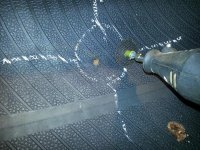
Having learned my lesson that the utility knife left a messy edge, on the inside wall of the tire, I used a Dremel tool cutting wheel to cut the rubber flush, which left a much nicer nub.
(see photo 2 below)

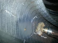
At this point, I tried the hand scraping tool, but it would have taken forever so I resorted to a wire wheel on the end of a drill, operated at less than 1,200 RPM. The marks I made outside the patch area came in handy, as the circle was nearly buffed away. In the future, I hope to buy a "cone buffer" which would have a better shape for the inside of the wheel, but for now, the wire buffer had to do (this was an experiment, so it's good to learn what tools are needed).
(see photo 3 below)

Here is the buffed area, ready to glob on the vulcanizing cement to let it try to tacky condition:
(see photo 4 below)

Peeling away the patch blue protective layer, I applied glue to the patch and stuck it onto the tacky glue on the tire and then stitched the patch down, going radially from the center outward.
(see photo 5 below)

The result is this inside patch over the external plug seen in the photo below.
(see photo 6 below).
 

Attachments

  • a09_dykes_dont_work.jpg
    a09_dykes_dont_work.jpg
    75.4 KB · Views: 1,140
  • a10_dremel_tool_works.jpg
    a10_dremel_tool_works.jpg
    112.1 KB · Views: 1,088
  • a11_wire_brush_cone_buffer.jpg
    a11_wire_brush_cone_buffer.jpg
    74.3 KB · Views: 1,212
  • a12_inside_buffed.jpg
    a12_inside_buffed.jpg
    116.9 KB · Views: 1,095
  • a13_stitching_down_patch.jpg
    a13_stitching_down_patch.jpg
    86.3 KB · Views: 1,049
  • a14_patch_stitched.jpg
    a14_patch_stitched.jpg
    78 KB · Views: 1,547
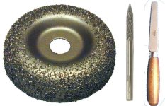
To do the job right, it seems, in retrospect, that I need three tools that I don't have.
1. Carbide bit (which cuts the steel belt and body cables flush)
2. Cone grinder bit (which has a better shape than a wire brush)
3. Flexible knife (which is better than the dremel disc cutter)

Here is an article which says not to use hand operated reamers:
You’ll never find the words “hand-reamer” or “drill bit” in any credible tire repair resource. A carbide cutter is specially designed to cut the damaged steel belt and body cables flush with the surrounding rubber. This stabilizes the area so the void can be filled with a cured rubber insert,

One lesson learned is that it's generally easy to ream the hole, but one of the holes was made by a staple-sized nail, which was nearly impossible to ream with the hand tool, simply because it wouldn't penetrate the thick rubber. For that hole, I just patched it from the inside; but in 20/20 hindsight, a reamer bit on a 1,200 RPM drill would have been what is needed for such a tiny hole if a plug was also to be used (which should be the case in all repairs).

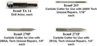
These reamer bits are surprisingly expensive (often thirty and forty bucks each), compared to what a drill bit would cost, for example, so there must be some reason for that unknown to me at the moment for the expensive ones, but I can find cheap bits for about five bucks (dunno how different they are though) where it seems you may need these four different sizes (just a smidge under 1/16th inch, a smidge under 1/8th inch, and a smidge under 1/4 inch):
 

Attachments

  • necessary_tools.jpg
    necessary_tools.jpg
    63.4 KB · Views: 1,091
  • forty_dollra_reamer.jpg
    forty_dollra_reamer.jpg
    25.1 KB · Views: 1,065
  • carbide_bit_sizes.jpg
    carbide_bit_sizes.jpg
    118.8 KB · Views: 1,052
Last edited:
Toyota 3rd-gen 4Runner Jack Stand Location (front & rear)

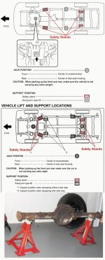
It was obvious where I "could" place my 6-ton 15-to-24-inch jack stands (aka safety stands) but it wasn't necessarily obvious where I "should" place jack stands, especially in the rear.

It turns out, I was using the wrong location since the only safe location in the rear is on the axle itself, apparently.

Searching this forum, I found the following information which may be useful to others performing the same task.
In the photo below, what do they mean by "without side step" and "with side step"?
(Is that just running boards? If it is running boards, why would they matter?)
 

Attachments

Last edited:
The rear axle is the best place for the jack stands if you're doing tire or brake work. If you are doing suspension work, you need to support it by the frame so you can drop the axle to get the weight off the springs.

Pretty much any place on the frame is strong enough to support the weight of the 4runner. The main thing for your personal safety is that whatever the jack stand is supporting sits squarely on the stand with no side forces, sloping surfaces, etc., that could cause the stand to suddenly slip sideways and eject itself from under the truck. Also look carefully at what is happening on the opposite side to where you are working. Sometimes jacking on one side will create an unsafe situation on the other side if you are not watching.

Add a backup stand or two, look everything over carefully for possible failure modes, shake the vehicle hard and check for instability, and then limit your time under the vehicle to as little as possible.
 
The rear axle is the best place for the jack stands if you're doing tire or brake work. If you are doing suspension work, you need to support it by the frame so you can drop the axle to get the weight off the springs.

Thank you for that interesting information as it seems this is a common question, where the answers are mostly jokes since everyone just assumes everyone else knows intuitively where to put the safety stands.

I, for one, put them in the front in the intuitive location, as I did the jack, both of which were correct.

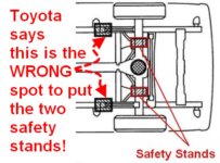
In the rear, I jacked in the intuitive location, which was correct, but I put the safety stands on the "joint" (swing arm?) in front of the wheel on the outside of the frame, which is apparently the wrong location for changing wheels.

It did seem a bit dodgy because there is only a "bulge" at that (swing arm?) bushing, so that's why I started looking up where the proper place for jack stands was.

It turns out that, at least according to Toyota, most of us are putting our safety stands in the wrong direction, but when you ask the question, most people ridicule the question.

I think it's a fair question, and I did my homework first, so, I do appreciate very much your clarification.

Pretty much any place on the frame is strong enough to support the weight of the 4runner.
I certainly understand your words, but that's not what the Toyota diagram says.

In general, there is usually a good reason Toyota says not to put safety stands at the point that I used just fore of the wheels at that bushing location.

What that reason is we should know before we use those points for our safety stands.
Do I know why Toyota doesn't suggest that point?
Nope.
It looked good to me. Intuitively anyway.
But it doesn't hold up to inspection.

The main thing for your personal safety is that whatever the jack stand is supporting sits squarely on the stand with no side forces, sloping surfaces, etc., that could cause the stand to suddenly slip sideways and eject itself from under the truck.
I certainly agree with you.
For example, I live in earthquake land, where you don't want to be under the vehicle when the ground starts heaving. To prevent the vehicle from falling, I generally shake the heck out of it just after I get it on the four 6-ton jack stands.

I also leave the jack under either the front brace or the rear differential, depending on which end I jacked up last (I'm lazy so I leave the jack just touching but not holding anything up).

Also look carefully at what is happening on the opposite side to where you are working. Sometimes jacking on one side will create an unsafe situation on the other side if you are not watching.
This is good advice, especially on softer surfaces or on sloping surfaces.

Add a backup stand or two, look everything over carefully for possible failure modes, shake the vehicle hard and check for instability, and then limit your time under the vehicle to as little as possible.

This is all good advice.
  1. I generally set the parking brake first & chock the rear
  2. Then I jack the front from under the crossmember
  3. I put the two 6-ton stands under the frame in the front (just aft of the wheels)
  4. I then move the jack to under the rear differential and jack it from there
  5. Then I position the two safety stands in the rear (I put them in the wrong spot!)
  6. Then I shake the vehicle like a Brazilian dancing girl!
  7. I leave the jack just touching the differential
  8. Sometimes (but rarely) I leave a wheel under the car also (if it's removed)
 

Attachments

  • safety_stands.jpg
    safety_stands.jpg
    52.8 KB · Views: 62,576
Status
Not open for further replies.

Members online

Forum statistics

Threads
278,315
Messages
3,554,130
Members
248,016
Latest member
Advally Service

Trending content

Back
Top