AOB switch and Black Oak lights wiring

airbusa380

New member
hi there (I have a 4runner 2016 SR5, did multiple searches and since I don't want to mess up the ECM I have to get this right ....I bought one pair of 2 inch pods LED spot lights and a light bar from Black Oak and I would like to wire them using 2 AOB switches that I have already .
I want to be able to use them when the ignition is ON only (not triggered by the high beams) with the dimming and illumination working.
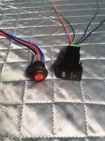
I'm sure the red green blue black wires coming out of the AOB is standard to all their switches...
my question is : I have black , red and blue wires going to the factory Black Oak harness switch , how do all these wires connect without making a mistake .
I read about using the wiper warmer switch but want to be sure ...
thanks, Erick.
 

Attachments

  • IMG_2581.jpg
    IMG_2581.jpg
    130.5 KB · Views: 4,017
Register to hide this ad
I was just about to post something similar. Doesn't seem to be a step-by-step write up anywhere. I only have the single AOB switch for my 30" bar and I'm terrified to mess it up.

Do i connect any wires from the light itself directly to the switch or does everything run through the relay? Confusing.
 
I don't know about the harnesses that come with other lights, so you may need to find out if your switches will handle the amps running straight thru if no relays are present.

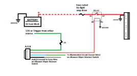
If wiring without a harness you can go by the diagram below.
[MENTION=140360]airbusa380[/MENTION], you will need to identify what each wire does obviously, but for the sake of both postings above, I wanted to include this diagram for both of you.
 

Attachments

  • AUX LIGHTS WIRING.png
    AUX LIGHTS WIRING.png
    20.7 KB · Views: 10,490
This link may help for using an AOB switch in lieu of the switch that came with the LED kit. I assume you have a good reason to wire both spots independently (like ditch lights), otherwise you could wire the two spots to a single harness and use one switch.

The 3 wires from the Black OAK switch are likely 1) Hot lead (12 volt positive +), 2) Relay trigger wire (connecting hot lead to this wire would engage/trigger relay turning on light bar), 3) Ground wire (negative -), but please check the wiring diagram that game with your harness.

As Saker's wiring diagram above, for illumination, the AOB switch wiring is:
Black - Connect to gray factory wire (- dimming)
Blue - Connect to green factory wire (+)
Red - Connect to relay trigger wire to power the relay when switch is engaged/turned on
Green - Connect to hot lead (ignition source in your case using adapter below to provide power when ignition is on)

Use THIS to tap into your fuse box for activating the switch with ignition on.

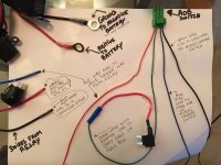
Picture courtesy of MTN4RNR.

DSC09599_zpspxrkicyt.jpg~original
 
Last edited:
Do i connect any wires from the light itself directly to the switch or does everything run through the relay? Confusing.

No, please see Saker's diagram above, you should use the relay to activate the secondary circuit which allows the battery power to flow to your LED. Basically the relay is allowing a lower amp circuit (connected to the switch) to safely power a higher amp circuit (LED light, fridge, compressor, etc).
 
I don't know about the harnesses that come with other lights, so you may need to find out if your switches will handle the amps running straight thru if no relays are present.

If wiring without a harness you can go by the diagram below.

[MENTION=140360]airbusa380[/MENTION], you will need to identify what each wire does obviously, but for the sake of both postings above, I wanted to include this diagram for both of you.

Saker , thanks... The black Oak pods come with harnesses and relays...
 
This link may help for using an AOB switch in lieu of the switch that came with the LED kit. I assume you have a good reason to wire both spots independently (like ditch lights), otherwise you could wire the two spots to a single harness and use one switch.

The 3 wires from the Black OAK switch are likely 1) Hot lead (12 volt positive +), 2) Relay trigger wire (connecting hot lead to this wire would engage/trigger relay turning on light bar), 3) Ground wire (negative -), but please check the wiring diagram that game with your harness.

As Saker's wiring diagram above, for illumination, the AOB switch wiring is:
Black - Connect to gray factory wire (- dimming)
Blue - Connect to green factory wire (+)
Red - Connect to relay trigger wire to power the relay when switch is engaged/turned on
Green - Connect to hot lead (ignition source in your case using adapter below to provide power when ignition is on)

Use THIS to tap into your fuse box for activating the switch with ignition on.

Picture courtesy of MTN4RNR.

DSC09599_zpspxrkicyt.jpg~original

Cutty01 thanks...I am not using two switches to operate the 2 spots just 1 switch ...what I meant was 1 switch for the spots and 1 switch for the light bar.
I will be using 2 factory harnesses for the 2 spotlights they each have a relay and inline fuse .
Both of these harnesses will be wired to one AOB switch.
 
Cutty01 thanks...I am not using two switches to operate the 2 spots just 1 switch ...what I meant was 1 switch for the spots and 1 switch for the light bar.
I will be using 2 factory harnesses for the 2 spotlights they each have a relay and inline fuse .
Both of these harnesses will be wired to one AOB switch.

Sorry, I misread. Good luck with your install. Please post pictures and tips once you get it done.
 
I don't know about the harnesses that come with other lights, so you may need to find out if your switches will handle the amps running straight thru if no relays are present.

If wiring without a harness you can go by the diagram below.

[MENTION=140360]airbusa380[/MENTION], you will need to identify what each wire does obviously, but for the sake of both postings above, I wanted to include this diagram for both of you.

Is that a 3amp Diode in on the green wire? The AOB instructions call for a 1amp. What does the 3A get you? Sorry for my newbish questions, Im limited in my understanding of electronics beyond installing speakers and basic stereo installs.
 
Is that a 3amp Diode in on the green wire? The AOB instructions call for a 1amp. What does the 3A get you? Sorry for my newbish questions, Im limited in my understanding of electronics beyond installing speakers and basic stereo installs.

Not a diode, it's a 3 AMP fuse shown.
 
Is that a 3amp Diode in on the green wire? The AOB instructions call for a 1amp. What does the 3A get you? Sorry for my newbish questions, Im limited in my understanding of electronics beyond installing speakers and basic stereo installs.

I was under the impression that a diode was not needed if the wiring was not of the high beam triggered type ?
 
Is that a 3amp Diode in on the green wire? The AOB instructions call for a 1amp. What does the 3A get you? Sorry for my newbish questions, Im limited in my understanding of electronics beyond installing speakers and basic stereo installs.

Usually, diodes are needed if you have two or more power sources feeding a single source input. For example, you would use a diode between the AOB switch and the relay if you used the switch to activate the relay and wanted the high beams to activate the relay also. The diode prevents back feeding of the power through the other circuit that could cause the other circuit to be possibly activated or damaged.

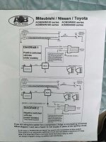
See the diagram below for negative switched vehicles. Note Saker and I are recommending slightly different wiring for the black wire so your switch dims with the illumination circuit.

154831d1429851568-aob-switch-install-question-negative-switched-headlights-not-aob.diagram.jpg
 
Last edited:
I was under the impression that a diode was not needed if the wiring was not of the high beam triggered type ?

[MENTION=140360]airbusa380[/MENTION],
My high beam circuit is my trigger, I have not had any issues with my setup on this and previous vehicles where I have run this setup.
I am not using a diode, only a fuse inline on the trigger wire.
I may try a 1 AMP fuse to see if it holds up, which it probably will....
Hope this helps.

Usually, diodes are needed if you have two or more power sources feeding a single source input. For example, you would use a diode between the AOB switch and the relay if you used the switch to activate the relay and wanted the high beams to activate the relay also. The diode prevents back feeding of the power through the other circuit that could cause the other circuit to be possibly activated or damaged.

See the diagram below for negative switched vehicles. Note Saker and I are recommending slightly different wiring for the black wire so your switch dims with the illumination circuit.

154831d1429851568-aob-switch-install-question-negative-switched-headlights-not-aob.diagram.jpg

[MENTION=128325]cutty01[/MENTION],
Thanks!
I just came back with my diagram and see you have already posted.
Appreciate the response!


Also:
 

Attachments

  • Scan.jpg
    Scan.jpg
    25 KB · Views: 2,175
Last edited:
Usually, diodes are needed if you have two or more power sources feeding a single source input. For example, you would use a diode between the AOB switch and the relay if you used the switch to activate the relay and wanted the high beams to activate the relay also. The diode prevents back feeding of the power through the other circuit that could cause the other circuit to be possibly activated or damaged.

See the diagram below for negative switched vehicles. Note Saker and I are recommending slightly different wiring for the black wire so your switch dims with the illumination circuit.

154831d1429851568-aob-switch-install-question-negative-switched-headlights-not-aob.diagram.jpg

Cutty01 thanks for your help and Saker too , your diagram does not match mine though look at the wires coming out of the switch ..which adds to my confusion and caution,
 

Attachments

  • IMG_2586.jpg
    IMG_2586.jpg
    131.6 KB · Views: 4,208
The only difference between DIAGRAM 1 and my diagram is I have a fuse on the trigger wire & the switch ground is not to earth, but to the grey wire on the wiper warmer circuit so the dimming will take place on the switch like the other switches.
 
Cutty01 thanks for your help and Saker too , your diagram does not match mine though look at the wires coming out of the switch ..which adds to my confusion and caution,

Could be cause the diagram I posted was the Aussie version of our model???? I would go with yours if it came with the switch, but the concept is the same just swap the red with green or visa versa.
 
This link may help for using an AOB switch in lieu of the switch that came with the LED kit. I assume you have a good reason to wire both spots independently (like ditch lights), otherwise you could wire the two spots to a single harness and use one switch.

The 3 wires from the Black OAK switch are likely 1) Hot lead (12 volt positive +), 2) Relay trigger wire (connecting hot lead to this wire would engage/trigger relay turning on light bar), 3) Ground wire (negative -), but please check the wiring diagram that game with your harness.

As Saker's wiring diagram above, for illumination, the AOB switch wiring is:
Black - Connect to gray factory wire (- dimming)
Blue - Connect to green factory wire (+)
Red - Connect to relay trigger wire to power the relay when switch is engaged/turned on
Green - Connect to hot lead (ignition source in your case using adapter below to provide power when ignition is on)

Use THIS to tap into your fuse box for activating the switch with ignition on.

Picture courtesy of MTN4RNR.

DSC09599_zpspxrkicyt.jpg~original


One last question now that I've had some time to wrap my brain around this. How did you run power from your light bar to power? Is it to the relay behind the battery? Just trying to figure out the entire path from the light to power to the switch. Man I wish there was a video for this!!
 
One last question now that I've had some time to wrap my brain around this. How did you run power from your light bar to power? Is it to the relay behind the battery? Just trying to figure out the entire path from the light to power to the switch. Man I wish there was a video for this!!

Not sure I understand your question, but Let me see if I can explain the wiring plan differently...

There are two circuits. The switch circuit and the LED (or other accessory) circuit. Switch triggers the relay, once triggered, the relay then allows battery power to flow to the LED or other accessory. The idea being, the lower power circuit of the switch, "activates" the higher amp circuit powering your LED or other accessory. That way you don't have high amps running through the interior of your vehicle.

The LED circuit receives power from the battery via the relay. You need an appropriately gauged wire (about 14 gauge for a LED but depends on watts of the LED and length between the positive terminal of the battery and LED so use a wire gauge chart to confirm) to connect the battery to the relay (pin 30). Usually a fuse is installed in between the battery and the relay as a safety measure. Then you run the same gauge wire from the relay (pin 87) to the positive terminal on the LED. Then you ground the LED. This completes the high amp circuit. Many people use the wiring harness that comes with the LED as this has the wiring already done for you and includes a relay. All you have to do is connect the red wire to the battery and the black wire to a ground.

The relay sometimes has its own separate ground on pin 85.

Now onto the switch circuit.

Let's eliminate the AOB specific wiring for now. Normally a switch that comes with the harness of your light bar will have three wires:
  1. Power wire (I have seen them red or white). On the harnesses I have seen, this wire goes to the relay (pin 30) where it is a combined with the positive wire from the battery. This is giving power to your switch so you don't have to wire it to a separate power source.
  2. A trigger wire (I have seen them blue or green). This wire is also going to the relay on pin 86 and energizes the relay causing it to "activate" the high amp circuit.
  3. A ground wire (I have seen them black or brown). This connects to a grounded screw or is connected to the relay (pin 85) and combined with the negative wire from the battery or separate ground.

If you are wiring a aftermarket 3-terminal switch to the relay then the wiring would be as follows:
  1. Power from the interior fuse box using the tap shown above. You do this if you only want the circuit live when you have the key in the ACC or in the ON position. That way you won't run down your battery if the switch is accidentally left on when the key is not in the ignition. Otherwise you can tap into an existing 12v source that comes on with the ignition. If you want the light bar to come on at any time, you choose a 12v source that is "always on".
  2. A wire (18 gauge is usually fine) to trigger the relay. This runs through the gourmet in the firewall to the relay (pin 86)in the engine compartment.
  3. A ground wire. This connects to a grounded screw in the interior thus completing the circuit.

Now with an AOB or similar switch, it's very similar, its just that there are extra wires to illuminate and dim the switch.

**EDIT from working airbusa380 - connect the green AOB wire to the fuse tap so your switch is activated via ignition. Connect the red AOB wire to the trigger wire coming from your harness. You will not need the power and ground wire from the light bar harness that was powering the switch that came with it.

Here are some useful videos and links:

If you still have questions, please ask again in a different way.

PS - I bought a SPOD as I knew I would have multiple accessories. It's expensive but sure is worth it. It has 6 switches and 6 relays all pre-wired. You connect the SPOD console to the battery in the engine compartment and then run the SPOD switch harness through the firewall to wherever you want to mount your 6 switches. Then for each accessory you want to power, you just connect the power and ground wire from the accessory to the SPOD console. That's it. no multiple strands of wire and no multiple relays all over the place. It also has a low voltage cut-off built in so if you leave an accessory on by accident, it won't drain your battery.

800-000-000-2.jpg


If you want a cheaper option of an "SPOD" look up Bussmann Fuse box. There are prebuilt ones on eBay but you have to do your own switch wiring.

Good luck.
 
Last edited:
Could be cause the diagram I posted was the Aussie version of our model???? I would go with yours if it came with the switch, but the concept is the same just swap the red with green or visa versa.

Cutty01 I'm still trying to make it work can you confirm that the diagram that I am posting right now is correct ? also the red wire coming out of the relay on the harness goes where?....

I realize its probably easy to figure out I just don't want to mess up anything ...

thanks (again)
Erick.
 

Attachments

  • IMG_2608aa.jpg
    IMG_2608aa.jpg
    129.6 KB · Views: 7,012

Members online

Forum statistics

Threads
278,316
Messages
3,554,113
Members
248,016
Latest member
Advally Service

Trending content

Back
Top